Adversarial Verification
15 Adversarial Verification
Purpose
Physical AI stack focus for this chapter.
Why can a machine pass its normal operating tests and still fail when its protective response is needed?
The claims that matter most in a physical machine describe what it does after something has already gone wrong, when the learned proposer stalls, an observation arrives old, a message is lost, or the supply sags while a loaded body moves toward a person. Normal operation almost never exercises those responses, so thousands of clean runs can coexist with a stopping mechanism that has never once been made to stop the machine. Without deliberate testing, the first real trial of that mechanism happens in service, where a late response delivers energy that no software correction can recall. Establishing such a claim requires creating the fault on purpose, measuring the physical response with instruments the fault cannot reach, and scoring it against acceptance conditions fixed before the test, and every condition left untested still limits what the result can support. Verification makes those limits explicit before release grants any action authority to cross the causal boundary.
Learning Objectives
- Derive test conditions and stopping oracles from the machine’s operating envelope
- Derive faults from design assumptions, physical hazards, authority-transfer failures, and attacks on the proposer and sensors
- Select qualification environments that exercise the causal mechanism behind each claim
- Design hardware injections with independent witnesses and precommitted acceptance conditions
- Interpret temporal safety margins and search for disturbances that violate them
- Evaluate the assumptions limiting simulation transfer, rare-event estimates, and formal proofs
- Assemble fault records that preserve failed, invalid, unobservable, and untested cases
15.1 The Claim a Fault Trial Must Test
The authority record at the close of Supervisory Intervention can log weeks of clean handovers and still say nothing about what the machine does when a duplicate writer appears on the bus, a stale packet replays, or a heartbeat drops—because none of those faults occurred during normal service. Every preceding chapter of this book rests on protective claims of the same kind: a chunk lease that expires within its declared deadline, a permission path that halts the mobile base within its clear distance, or a safety microcontroller that outlasts a voltage brownout on the shared electrical supply. Because those fallback paths stay dormant until a subsystem breaks, an unexpected fault discovered in service has already crossed the causal boundary into the room, releasing kinetic energy that no software update can undo. Verification turns these design assertions into auditable evidence by provoking each fault deliberately before release, under the physical loads that make the protective response hardest to execute.
A trial passes only when an independent sensor witnesses the act.
Policy evaluation measures how capably a learned candidate policy completes tasks across declared environments. Verification, by contrast, tests the integrated machine as a whole: proposer, runtime enforcer, communication buses, power distribution network, and physical body. High task completion rates during policy evaluation do not show that an independent emergency stop engages when the neural proposer hangs; conversely, a reliable emergency stop does not show that the learned policy navigates aisles smoothly. Qualifying an embodied machine requires both kinds of evidence gathered on the same production hardware and software stack. The same distinction separates raw policy autonomy from whole-machine safety, because an enforcer applying a least-change correction can keep the robot safe during a mission while isolating and logging a hazardous proposal from the model.
⇄ Contrast: Policy evaluation, which scores the learned proposer’s task proficiency rather than the whole machine’s protective responses, is established in Closed-Loop Evaluation.
1 Digital Twin: Grieves and Vickers (2017) trace the concept to a 2002 presentation on product lifecycle management, and Glaessgen and Stargel (2012) gave it the sense aerospace adopted, a simulation of one as-built vehicle, updated continually from that vehicle’s own sensors and history so that it mirrors the life of its flying twin. The original meaning therefore depended on continual calibration against one particular physical article. A simulator that has never been compared with a measured stop of this machine is a model, not a twin, and treating it as a twin is the delusion this chapter names.
Grieves, Michael, and John Vickers. 2017. “Digital Twin: Mitigating Unpredictable, Undesirable Emergent Behavior in Complex Systems.” In Transdisciplinary Perspectives on Complex Systems, edited by Franz-Josef Kahlen, Shannon Flumerfelt, and Anabela Alves. Springer. https://doi.org/10.1007/978-3-319-38756-7_4.
Glaessgen, Edward, and David Stargel. 2012. “The Digital Twin Paradigm for Future NASA and U.S. Air Force Vehicles.” 53rd AIAA/ASME/ASCE/AHS/ASC Structures, Structural Dynamics and Materials Conference. https://doi.org/10.2514/6.2012-1818.
Treating passing assertions in a software simulator as sufficient proof of physical safety is the digital twin delusion.1 A physics engine or digital emulator models timing jitter, power transients, and floor traction only to the extent that its authors anticipate and calibrate those effects; a simulated controller cannot fail on an unmodeled supply sag or bus collision. Passive operational logs invite an equally dangerous complacency: millions of incident-free operating hours show only that severe corner conditions did not arise during benign runs, leaving dormant failure modes untested.
Adversarial fault injection answers both traps by turning a design claim into a controlled disturbance executed inside an independent physical containment cell. To count as engineering evidence rather than an ad hoc stress test, a fault trial must declare its operating-envelope point, score telemetry against precommitted oracles that leave no room for after-the-fact negotiation, and preserve cryptographic records of the hardware and software state. The campaign then reports which points across the envelope those trials actually cover while the test harness records how each fault propagates across power rails, fieldbuses, and mechanical brakes.
Consider the warehouse mobile manipulator navigating an aisle at 1.3 m/s (chosen; see the Reader Guide) toward a rack end where a pedestrian may step out from a blind intersection. The learned proposer might abruptly stop renewing motion commands while the base continues rolling under momentum. An architectural authority diagram specifies which subsystem must take over, but that specification does not prove that the physical permission path survives the crash or that mechanical brakes engage before impact. An empirical trial that induces the fault and measures physical motion supplies evidence for the named protective response under its declared conditions. To structure that trial, the test harness must reflect how the machine partitions execution across its physical substrates: an application system-on-chip (SoC) equipped with an embedded accelerator executes the unprivileged learned proposers (the vision-language-action intent model and the chunk policy beneath it), while a lockstep safety microcontroller executes the deterministic runtime enforcer. The safety microcontroller commands the base-drive motor inverters across a hard real-time fieldbus (EtherCAT, or Controller Area Network with Flexible Data-Rate, CAN FD) whose cyclic frames arrive on a strict, microsecond-scale schedule. Both processors draw power from the shared 47.7 V drive bus that powers the traction motors: the application SoC through a buck-boost converter, and the safety microcontroller through an isolated converter backed by a dedicated, held-up permission rail.
Weeks of uneventful operational logs at that speed say little about four severe hardware and timing faults that the architecture claims to contain:
- Proposer Stall (F1): The chunk policy, the fast proposer of Two proposers and the evidence horizon that renews motion every 50 ms, has its latest proposal successfully admitted by the permission path, renewing its chunk lease, but immediately suffers a thread deadlock, driver lockup, or thermal throttling freeze.
- Stale Observation (F2): A camera frame or depth tensor arrives at the permission path with an aged or corrupted hardware timestamp after silent queuing in an image signal processor (ISP) buffer or direct memory access (DMA) ring.
- Lost Fieldbus Frames (F3): Electromagnetic interference (EMI) from high-current inverter switching corrupts or drops a burst of EtherCAT or CAN FD frames between the safety microcontroller and the wheel actuators.
- Drive-Bus Droop and Feed Loss (F4a/F4b): A supply injector steps the shared 47.7 V drive bus below the 33 V lockout threshold of the converter feeding the application processor under the declared drive load (F4a), or the permission rail itself loses its primary electrical feed (F4b).
These physical failure modes F1–F4, paired with the supervisory authority transfer faults A1–A4 (formalized in table 2), organize the entire verification campaign. In theory, each threat has a dedicated countermeasure: the lease detects a hung proposer, the evidence-epoch check discards stale sensor frames, the fieldbus watchdog flags dropped communication cycles, and the isolated undervoltage supervisor manages electrical brownouts. In practice, adversarial verification injects each disturbance as the robot approaches the rack end, alongside the four authority handoff faults that the authority record hands over (Per-tick evidence tuples and the fault injection suite), and scores every stopping trial against temporal and distance bounds derived from the machine’s own stopping budget.
An injected fault converts a physical trial into valid evidence for an auditable safety case only when the experiment satisfies the five requirements of the cyber-physical test contract:
- A bounded claim: The test specifies the exact invariant the machine must maintain. For the mobile base at the rack end, the machine must come to a complete stop within the 1.10 m clear distance.
- Defined test conditions: The specification bounds every relevant physical variable, including initial velocity, payload mass, floor friction, ambient operating temperature, bus traffic saturation, and DC supply voltages.
- A precommitted oracle: An automated evaluation harness inspects captured telemetry against the claim without human intervention, retrospective threshold tuning, or post-hoc excuses (section 15.4 defines the oracle formally).
- A stated sampling and injection procedure: The test harness exercises the machine systematically across its operational envelope, deliberately triggering faults in sensors, buses, power rails, and actuators during peak mechanical and computational load.
- Provenance: The campaign logs complete cryptographic digests of model weights, calibration tables, sensor serial numbers, oscilloscope traces, and raw bus logs to enable matched re-execution. Software builds can be reproduced bit for bit; a physical trial can be replicated only when repeated under physical conditions that match declared tolerances.
The base’s stopping claim and the manipulator arm’s latch-force claim require separate operational envelopes, injection points, and acceptance criteria; this chapter follows the mobile base’s stopping claim. Fixing the contract starts with its second element, the declared conditions under which the claim must hold, which also locate the point beyond which nominal regulation must yield to an independent containment response.
15.2 The Operating Envelope
A mobile robot carrying a full payload down a warehouse aisle stops in a very different distance when memory-bus contention delays its perception pipeline, when battery supply rails sag under acceleration, or when drive inverters heat up under sustained torque. Specifying the external operational design domain (ODD) alone therefore leaves the test conditions half-defined; an operating envelope couples those external conditions with the internal execution state of the computing, power, and actuation hardware. Every protective claim must declare both dimensions—the environmental bounds and the internal computational and electrical loads—under which it is guaranteed to hold.
For the mobile manipulator, the operating envelope declares the range of conditions over which the protective claim must hold. The campaign samples a discrete set of qualification points within that range; extending their results to untested points requires an explicit coverage argument. These points span an aisle speed of 1.3 m/s, payload masses ranging from an unloaded chassis to the full 50 kg rack capacity, and ambient operating temperatures from 5 °C to 35 °C. Surface friction must also be parameterized explicitly. In an optimistic all-weight traction screen, dry aisles require a friction coefficient of at least 0.204 to support the design braking deceleration of 2 m/s², whereas areas under the facility floor inspection regime guarantee only 0.12. The screen assumes that the driven wheels carry the entire weight; the actual base requires a qualified loaded deceleration that respects driven-wheel load share, configured braking current, and tip stability. For these inspected surfaces, the screen identifies a candidate restricted point at 1 m/s, whose friction premise must be logged in the enforcement telemetry. Verification trials on inspected floors must run against a physical test surface calibrated to this 0.12 threshold and must recalculate the oracles from the qualified loaded deceleration before testing the actual base.
Each physical configuration couples directly to the machine’s internal execution state. Trials must evaluate application-processor utilization driven to peak neural inference bursts, drive-bus voltages sweeping from a depleted 42 V up to a nominal 47.7 V, transmission jitter across EtherCAT or CAN FD buses, DRAM crossbar contention, and the thermal state of the safety microcontroller. The verification campaign also challenges transient edge conditions, chief among them a human takeover while the base is moving. Clearance-derived fallback deadlines screens a candidate in-loop takeover, with its 605 ms conservative response-and-exchange allowance, at the 0.75 m/s slow-down; the same moving handover is infeasible at the 1.3 m/s aisle speed and must be rejected. The slow-down remains a qualification candidate, conditional on operator response, admission delay, current clearance, and a feasible stopping continuation. The operative design stops the base before handing over. Both speeds therefore belong in the campaign, one to challenge a candidate moving transition and one to verify its rejection. Whenever an authority transition cannot preserve the verified stopping envelope, the enforcer must execute a local stop.
↩︎ The rule that an authority transition unable to preserve the stopping envelope ends in a local stop is established in Clearance-derived fallback deadlines.
Definition 15.1: Operating envelope
Operating envelope is the declared set of external conditions and internal execution states, each point stated with its units and tolerances, over which a machine’s protective claim must hold and at which every trial of that claim is run.
- Significance: The envelope governs which terms of the inequality \(\StoppingDistance \le \ClearDistance\) are stressed during an empirical trial. For the running machine, an aisle speed of 1.3 m/s falls below the optimistic 1.44 m/s ceiling on a dry floor, yet exceeds the 1.23 m/s ceiling on an inspected surface. The identical velocity therefore passes the all-weight screen on one surface and fails it on another; passing still requires loaded qualification before admission.
- Distinction: The operational design domain describes the external environment encountered by the planning policy. The operating envelope expands this definition to incorporate internal machine states, including processor utilization, drive-bus voltages between 42 V and 47.7 V, and communication bus saturation. The same physical aisle yields vastly different safety margins under memory contention or electrical depletion.
- Common pitfall: A frequent mistake is treating an operating envelope as a simple Cartesian product of decoupled intervals, assuming that testing each parameter independently at its minimum and maximum guarantees coverage. In cyber-physical systems, multi-dimensional boundary couplings are the rule rather than the exception: two parameters operating well within their nominal isolated bounds can combine to trigger an unrecoverable failure. Robust verification demands testing directly at these coupled, high-stress corners.
An operating envelope must be distinguished from the wider survival envelope that encloses it. Within the operating envelope, the learned policy and low-level tracking controllers regulate nominal behavior. When an external disturbance, sensor dropout, or compute stall pushes the machine across that boundary, nominal control yields to safety mechanisms that bring the robot to a bounded, safe stop before structural limits are violated. For the mobile manipulator, the survival envelope must be characterized separately for each fallback response and machine state. The standard resident stop executes controlled, powered deceleration before setting electromechanical holding brakes at zero velocity. In contrast, torque inhibit prevents commanded torque generation without necessarily electrically isolating the drive; it does not follow the controlled stopping profile or inherit its stopping-distance budget. If the remaining containment mechanisms cannot absorb the motion, structural damage may result when kinetic energy (\(\KineticEnergy = \frac{1}{2} \Mass \ImpactSpeed^2\)) exceeds what mechanical compliance and chassis end-stop dampening can absorb before hard impact. For the base in a test cell, the survival envelope is therefore the set of states from which the qualified combination of torque inhibit, passive resistance, holding mechanisms, and compliant end-stops can contain the remaining motion and energy. That boundary, not the clear distance of the stopping claim, is what the test cell’s own protection watches.
↩︎ The fallback rungs, from the controlled resident stop to hardware torque inhibit, are established in The four rungs of the fallback ladder.
Establishing envelope boundaries requires deriving physical constraints from first principles rather than asserting arbitrary software timeouts. In rack-end operations, this boundary is governed by the stopping budget. Total stopping distance scales linearly with pre-braking latency and quadratically with vehicle speed (equation 2.2). In the conditional design budget of The warehouse mobile manipulator's stopping budget, a pre-brake subtotal of 133.6 ms measured from sensor capture, combined with the jerk-limited resident stop and the tracking inset, yields a partial-budget speed ceiling of 1.44 m/s on a dry floor. That ceiling holds only before the dispatch-to-admission interval is charged, and The board-link budget and the dispatch-to-admission interval allocated that interval without yet measuring it. Running at the candidate aisle velocity of 1.3 m/s consumes 969.0 mm of the available 1.10 m clearance. The unallocated spare of 131.0 mm, which the vehicle crosses in 100.8 ms, must still absorb that interval. Its allocation of 63.3 ms costs 82.3 mm of travel at this speed and leaves 48.7 mm, or 37.5 ms of waiting, the same remainder that Clearance-derived fallback deadlines found for a human takeover at aisle speed. The full 100.8 ms is therefore a ceiling, the longest dispatch-to-admission interval the spare could pay for. When later examples in this chapter quote the full spare, they quote an upper bound on the unbudgeted delay the machine can tolerate; once the allocation is charged, only the remainder is left to spend.
↩︎ The jerk-limited resident stop and its stopping distance are established in The C^2 stopping suffix and jerk-limited braking.
Two conditional oracle bounds follow from that budget. Before any qualification trial, the harness must show that the bounds cover the whole execution path from the reference event to rest, because an interval left unallocated is an open qualification gap rather than a margin.
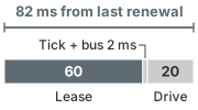
Of the 82 ms onset deadline, the lease takes 60 ms.
- Powered Deceleration Onset Deadline: Powered deceleration must begin no later than 82 ms after the last valid renewal. This deadline traverses the full permission and actuation chain: the 60 ms lease duration, a single 1 ms tick of the safety permission loop, one 1 ms communication bus cycle, and the 20 ms drive latency from delivered stop command to physical deceleration onset. (For the power-rail fault scenario F4, the onset deadline is referenced instead to the assertion of the hardware undervoltage flag.)
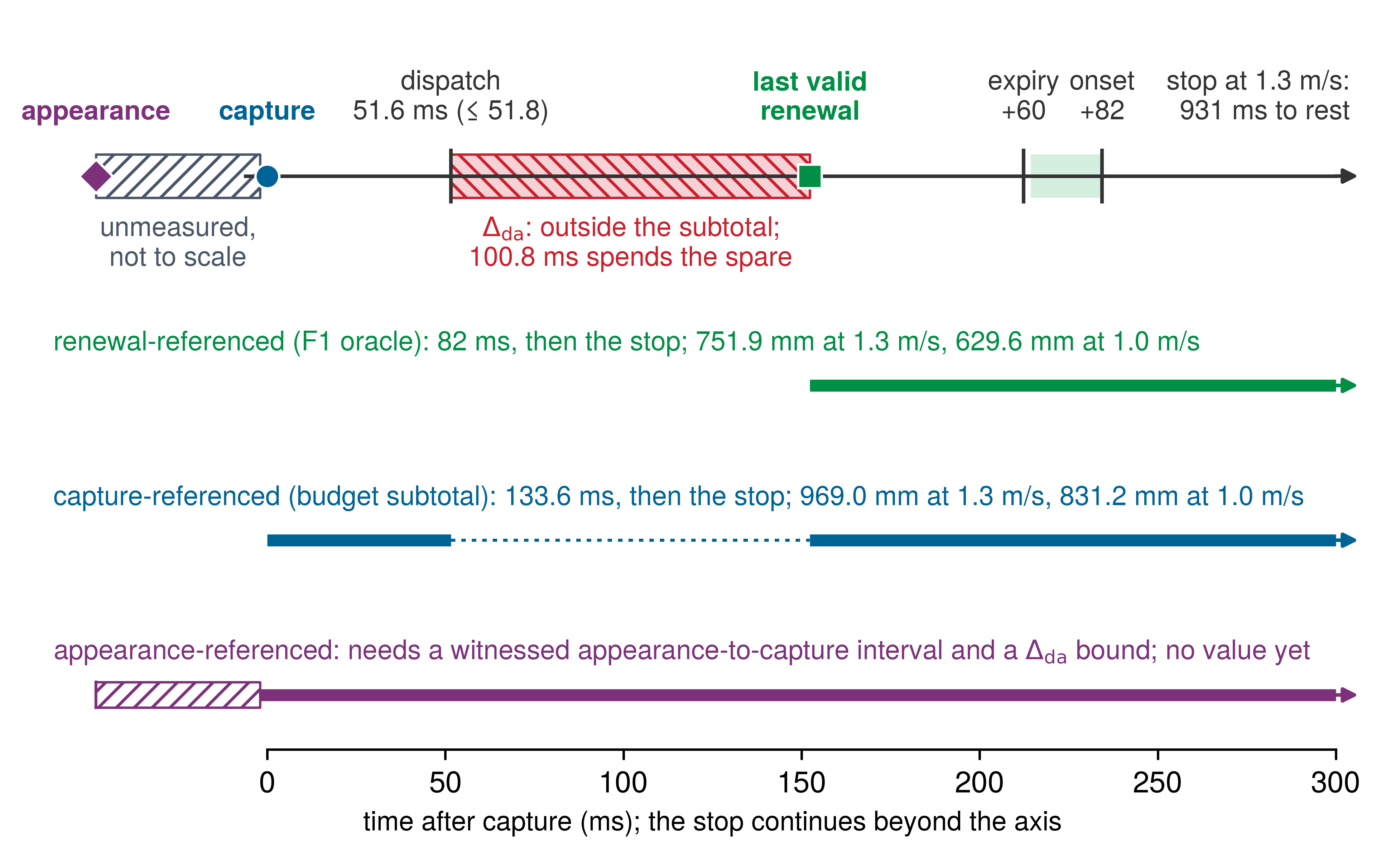
- Stopping Distance Bound: The vehicle, tracked by external optical instruments independent of onboard odometry, must come to rest within the distance allocated from the reference event that triggers the fault. Three reference events are possible, and figure 1 places them on one time axis. A capture-referenced trial measures clearance and displacement from the exposure midpoint of a qualified sensor capture; the 969.0 mm subtotal starts there but omits the dispatch-to-admission interval, so it is incomplete until that interval is added. An appearance-referenced trial starts earlier, at the optical appearance of an unheralded hazard; it must timestamp that appearance and the first usable capture independently, and add the travel between them, as well as the dispatch-to-admission travel, to obtain a complete bound against the clearance measured at appearance. A renewal-referenced trial applies when a stalled proposer produces no new target at all; it scores both stopping distance and onset latency from the last valid lease renewal. No trial may claim a pass against an incomplete budget subtotal.
↩︎ The lease path, from the last admission through the permission tick and bus cycle to brake onset, is established in Chunk Lease Sizing from the Stopping Budget.
Measured from that event, the two F1 verification predicates are (equation 1): \[\HazardOnset \le \ChunkLease + \PermissionLoopPeriod + \CommandTransportTime + \ActuatorResponseTime, \qquad \StallTravelBound(\SpeedAtDetection) = \SpeedAtDetection\,(\ChunkLease + \PermissionLoopPeriod + \CommandTransportTime + \ActuatorResponseTime) + \ResidentStopDistance(\SpeedAtDetection) + \TrackingErrorBound \tag{1}\] Here \(\HazardOnset\) is the measured interval from the last valid renewal to the physical onset of powered deceleration, \(\StallTravelBound(\SpeedAtDetection)\) bounds the measured travel from that renewal to rest, \(\ResidentStopDistance(\SpeedAtDetection)\) is the jerk-limited resident stop profile from equation 11.17, and \(\TrackingErrorBound\) is the tracking inset. The design budget’s pre-brake subtotal \(\PrebrakeDelay\) begins earlier, at raw sensor capture, and its sum also carries the localization bound and the protective margin. Notebook 15.1 evaluates both sums at the rack end.
Napkin Math 15.1: The reference-event gap
Problem: A proposer stall at the aisle speed is scored from the last valid renewal. What onset and travel bounds follow from the lease path and the resident stop, and how far below the capture-referenced subtotal of the design budget do they sit?
Variables:
- \(\SpeedAtDetection =\) 1.3 m/s (Chosen) and \(\ClearDistance =\) 1.10 m (Illustrative; The running machine's card).
- \(\ChunkLease =\) 60 ms and \(\PermissionLoopPeriod =\) 1 ms (Chosen); \(\CommandTransportTime =\) 1 ms and \(\ActuatorResponseTime =\) 20 ms (Illustrative).
- \(\CredibleBrakingDeceleration =\) 2 m/s² (Illustrative; stands in for a measured loaded deceleration) and \(\JerkLimit =\) 7.11 m/s³ (Derived; the reference stop polynomial’s peak jerk).
- \(\TrackingErrorBound =\) 40 mm and \(\LocalizationBound =\) 50 mm (Illustrative); \(\ProtectiveClearanceMargin =\) 100 mm (Chosen); evidence age \(\ObservationAge =\) 51.6 ms (Derived; The latency waterfall).
Math:
Onset bound. \[t_{\text{onset}} \le T_{\text{lease}} + T_{\text{tick}} + T_{\text{bus}} + T_{\text{act}} = 60 + 1 + 1 + 20 = 82\ \text{ms}\]
Resident stop (equation 11.17). \[d_{\text{suffix}}(v) = \frac{v^2}{2a_{\text{brake}}} + \frac{v\,a_{\text{brake}}}{2j_{\max}} = \frac{1.3^2}{2 \times 2} + \frac{1.3 \times 2}{2 \times 7.11} = 0.4225 + 0.1828 = 0.6053\ \text{m}\]
F1 oracle from the last valid renewal (equation 1). \[d_{\text{F1}}(v) = 1.3 \times 82 + 605.3 + 40 = 106.6 + 605.3 + 40 = 751.9\ \text{mm}\]
Capture-referenced subtotal, which leaves 131.0 mm of the clear distance. \[v\,\tau_{\text{delay}} + d_{\text{suffix}} + \delta_{\text{loc}} + \delta_{\text{margin}} + \epsilon_{\text{track}} = 1.3 \times 133.6 + 605.3 + 50 + 100 + 40 = 969.0\ \text{mm}\]
The gap between them. \[969.0 - 751.9 = 1.3 \times 51.6 + 50 + 100 = 67.1 + 150 = 217.1\ \text{mm}\]
Sensitivity. In the optimistic all-weight screen at the restricted point on the inspected floor, friction caps the deceleration at 1.18 m/s²: \[d_{\text{F1}}(1) = 1 \times 82 + \left(\frac{1^2}{2 \times 1.177} + \frac{1 \times 1.177}{2 \times 7.11}\right)\text{m} + 40 = 82 + 507.6 + 40 = 629.6\ \text{mm}\] A speed reduction of 23.1 percent shortens the oracle distance by only 16.3 percent, because the diminished traction cancels out the majority of the kinematic savings.
Result: F1 passes only if powered deceleration begins within 82 ms and the base travels at most 751.9 mm from the last valid renewal, 217.1 mm less than the capture-referenced subtotal.
Systems insight: Both formulations share the identical deceleration trajectory \(\ResidentStopDistance(\SpeedAtDetection)\); they diverge entirely on their reference event. The design subtotal incorporates 67.1 mm of evidence-age travel alongside the localization bound and protective margin that protect a detected target. However, a stalled proposer produces no target. If the verification harness evaluated an F1 proposer stall against this generous capture-referenced subtotal, the distance predicate would tolerate a braking onset roughly 167 ms late, more than double the entire onset deadline. Verifying the fundamental invariant \(\StoppingDistance \le \ClearDistance\) remains sound only when travel is measured strictly from the physical or temporal event that the fault disrupts.
The partial budget beneath both bounds reproduces the arithmetic of the design record, serving as a conditional oracle specification rather than empirical timing closure. A physical trial must directly instrument and log successful admission timestamps, continuing evidence age, and physical deceleration onset. Nominal proposer loop cadences cannot guarantee that lease renewals succeed before the deadline expires. Because a safety lease begins strictly upon successful admission, the renewal verification campaign must qualify the maximum inter-admission interval demanded by the lease rule (equation 4.4) under realistic compute contention, bus saturation, and rejected proposals, rather than measuring only unvetted proposer dispatch timestamps.
Both oracle bounds also assume that the safety permission pipeline, required perception channels, and powered traction drives survive the injected fault. Capacitive hold-up for logic rails and brake coils cannot sustain the traction drives during heavy braking. The power-loss fallback (F4b) must therefore maintain and monitor a verified auxiliary power reserve and dynamic braking dissipation path throughout deceleration. If an injected fault disables these electrical reserves, the system drops into an unpowered fallback mode whose stopping envelope must be characterized independently. Neither oracle bound relies on corrective action from either learned proposer. When the chunk policy stalls, it cannot delay braking onset: the hardware safety monitor issues the stop when the lease timer expires, with physical onset following the allocated tick, bus, and actuator path, cleanly isolating safety enforcement from proposer latency. The F1 qualification test thus benchmarks the deterministic safety permission path rather than the learned policy. Finally, this stopping budget assumes a static obstacle located at the clearance boundary. Static verification trials do not validate protection against dynamic agents moving toward the machine; site crossing restrictions and occluded-motion tracking must cover that case. Declaring these qualification points alongside both formal bounds provides the complete specification required to execute an empirical verification trial.
↩︎ Tracking a moving body through occlusion, which this static-obstacle budget does not cover, is established in Forward State Propagation and Occlusion Decay.
15.3 One F1 Trial from Injection to Record
The campaign’s first trial is F1, a proposer failure during transit, planned at the candidate restricted envelope point of 1 m/s with the full declared payload on a test floor qualified to the inspected friction. The numerical oracle remains a screening specification until loaded braking qualification supplies the actual deceleration bound. The safety claim under test is conditional. Once trajectory proposal renewals cease, the low-level permission path and motor drives must autonomously execute the resident powered stop within their allocated stopping envelope. The test deliberately halts or freezes the chunk policy immediately following its last valid lease renewal while leaving its underlying timer heartbeat active. This fault pattern cleanly separates true algorithmic progress in the proposer from the superficial liveness of an unblocked timer interrupt.
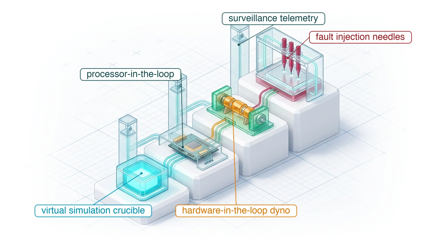
Verifying this stopping claim in its entirety requires a full physical rig: the production mobile base, motor drives, representative payload mass, and a qualified test surface. A processor-in-the-loop (PIL) bench, which runs the enforcer’s compiled binary on its target microcontroller against a simulated plant, can validate lease expiration but not the plant’s response, and a pure software simulation approximates both the target’s execution timing and the contact mechanics. Neither bench environment alone provides empirical ground truth for physical stopping distance. Because the machine operates at the edge of its operational envelope during fault injection, an external physical containment fixture must guard the testing volume independently of whatever safety action the machine itself takes.
The temporal reference event for F1 is the last successful admission check that renewed the trajectory lease, not the upstream planner dispatch or the subsequent fault injection trigger. A complete diagnostic trace captures both the final renewal and the injection event across isolated hardware channels that independently record lease expiration, the permission path’s stop command, the physical onset of powered deceleration, and external tracking of base position through complete standstill. Calibrated motor-current or torque measurements alongside wheel encoders identify drive effort and wheel response; external base-motion tracking is still needed to establish chassis deceleration under possible wheel slip. Timing uncertainty belongs in the onset margin. An auxiliary contact switch on the mechanical brake verifies subsequent holding-brake engagement. Relying on the mechanical brake switch alone would mischaracterize stopping latency, as it cannot record the initial phase of regenerative or active electric braking.
Capturing the machine’s state trajectory, fault detector identity, refusal timestamp, and recovery time to a safe state demands instrumentation that is electrically and logically decoupled from the robot, such as external optical ground-truth cameras and optical shaft encoders routed to isolated digitizers. An onboard logging daemon cannot serve, because the fault under evaluation, whether a panicked kernel or a saturated interconnect bus, delays or drops the very log it would write.2 Independent external measurement helps expose false passes, where an anomalous run appears successful for reasons outside the formal safety claim. For example, injecting a dropped-frame fault might unintentionally trigger an unmonitored thermal breaker or an auxiliary ground loop that cuts drive power. If that happens, the spring-applied mechanical brake halts the base well within the distance budget, even while the software safety enforcer remains deadlocked in a priority inversion. A naive verification oracle that checks only final stopping distance would mark that trial as a success. A rigorous test harness must verify that the exact causal enforcer path specified in the safety claim commanded and governed the deceleration.
2 Probe Effect: Gait (1986) identified the probe effect in concurrent software systems, where the overhead of monitoring instrumentation alters execution timing, inadvertently masking or introducing race conditions. On-chip hardware trace units, such as Arm’s CoreSight Embedded Trace Macrocell, stream cycle-accurate instruction flows over dedicated trace pins, while external protocol analyzers monitor bus transactions without altering bus arbitration. A verification trial must time the enforcer’s reaction using non-intrusive hardware instruments rather than software logging daemons executing on the processor under test.
Gait, Jason. 1986. “A Probe Effect in Concurrent Programs.” Software: Practice and Experience 16 (3): 225–33. https://doi.org/10.1002/spe.4380160304.
Superficial liveness signals are a second source of false passes. Supervisory timers and proposal wire contracts required that a watchdog be refreshed only when a safety-critical cycle completes, never from an independent periodic interrupt, and grounded the rule in the Toyota unintended-acceleration litigation, where expert testimony argued that a timer interrupt could keep a hardware watchdog satisfied after the control tasks had stopped (Barr 2013). A design rule on paper does not show that the built machine obeys it, and F1 is the test of whether it does. The harness halts the chunk policy’s task or freezes its command output while keeping the periodic interrupt handler alive (perspective 15.1), and it measures the actuator response and watchdog state with external instruments. A host daemon can keep reporting a valid process heartbeat after the policy inference thread has frozen, so trial F1 passes only when physical deceleration onset is recorded at the motor drives, never on the strength of a software heartbeat logged in memory. The Toyota record adds a second question that the design rule alone does not raise, whether the supervising monitor shares an input with the processor it supervises (war story 15.1).
Systems Perspective 15.1: The watchdog liveness invariant
A watchdog serviced by a periodic timer interrupt proves only that the timer interrupt service routine executed, not that safety-critical application tasks met their deadlines, computed valid outputs, or avoided memory corruption. A qualified fault-injection campaign explicitly decouples application progress from interrupt liveness, verifying that the system initiates physical shutdown under task termination, thread starvation, and frozen control registers.
War Story 15.1: Testing a task-blind watchdog hypothesis
Context: In Bookout v. Toyota (Oklahoma County, 2013), a jury heard expert testimony on the electronic throttle control system (ETCS-i) of a 2005 Camry. The plaintiffs’ software expert argued that safety-critical control tasks could fail silently while supervisory mechanisms remained blind to the failure (Barr 2013). Supervisory timers and proposal wire contracts drew its watchdog rule from this testimony; the same record also bears on a second claim, the independence of the monitor that backs the watchdog.
Mechanism: The engine control module serviced its hardware watchdog from a recurring timer-tick interrupt rather than requiring verified progress from active control tasks. The expert testified that if the task managing throttle angle and critical fail-safes terminated due to memory corruption or a stack overflow, the throttle command could freeze at its last valid state while the timer interrupt continued to pacify the watchdog (Barr 2013). The architecture included a secondary monitor processor, but testimony highlighted that this monitor could not inspect task scheduling; it could detect a dead throttle task only indirectly, through changes in brake-pedal state. A single analog-to-digital converter also digitized accelerator-pedal position for both processors, placing a common-cause failure point across the supervision boundary (Dunn 2013). Recovery could therefore require the counterintuitive act of lifting a foot off the brake during the event.
Impact: On October 24, 2013, the jury awarded $3 million in compensatory damages and found that Toyota had acted with reckless disregard; the parties settled before the jury could consider punitive damages (Safety Research & Strategies 2013). The verdict did not establish an uncontested technical cause. NASA’s engineering review for the federal investigation found no evidence that an electronic malfunction caused large unintended accelerations (NASA Engineering and Safety Center 2011). It did document electronic faults, among them a tin whisker that formed a 248 Ω short within an accelerator-pedal position sensor from a 2003 Camry; vehicle tests confirmed that while this fault altered how the throttle tracked the pedal, the throttle still returned to idle whenever the pedal was released (Leidecker et al. 2011). The investigation attributed the explainable incidents to floor-mat entrapment, sticking pedals, and pedal misapplication. The task-blind mechanism therefore remains an attributed hypothesis, which is exactly the kind of claim only injection can settle.
Response: For the design under test, fault injection must establish which application progress checks reach the watchdog, verify whether the independent monitor shares any input pathway with the processor it supervises (section 15.6.2), and confirm which protective inputs can reliably command a physically suitable stop. The historical controversy highlights the danger, but only direct injection testing establishes these properties for the warehouse machine.
Systems lesson: A periodic watchdog heartbeat confirms only that an interrupt handler continues to cycle, not that application tasks are functioning, and a monitor is independent only if no input, supply, or clock it depends on can fail together with the processor it supervises. Verification must therefore terminate the supervised task and inject faults at those shared points, measuring the actuator response with external, isolated instruments.
Leidecker, Henning, Lyudmyla Panashchenko, and Jay Brusse. 2011. Electrical Failure of an Accelerator Pedal Position Sensor Caused by a Tin Whisker and Discussion of Investigative Techniques Used for Whisker Detection. 5th International Tin Whisker Symposium.
NASA Engineering and Safety Center. 2011. Technical Support to the NHTSA on the Reported Toyota Motor Corporation (TMC) Unintended Acceleration Investigation. National Aeronautics; Space Administration.
Safety Research & Strategies. 2013. Toyota Unintended Acceleration and the Big Bowl of “Spaghetti” Code.
Dunn, Michael. 2013. Toyota’s Killer Firmware: Bad Design and Its Consequences. EDN.
Barr, Michael. 2013. Bookout v. Toyota Motor Corp.: 2005 Camry L4 Software Analysis.
Safety intervention mechanisms must be evaluated under the exact operational stress that makes intervention necessary. A safety enforcer that takes over cleanly on an idle development bench offers little assurance for a production vehicle. In an operational emergency, the policy model operates at maximum inference throughput, memory buses are saturated with high-resolution sensor streams, DMA controllers move camera frame buffers, and the mobile base carries its loaded rack at aisle speed. The verification framework therefore injects faults under declared worst-case thermal and electrical loads, measuring both lease-expiration revocation latency and the elapsed time between diagnostic fault assertion and powered deceleration onset at the motor drives. If the intervention path shares a system bus or memory arbiter with the neural accelerator, safety takeover can stall behind an unpreemptible burst transfer. A safety case that assumes near-instantaneous intervention without a contention bound can credit a response the deployed hardware cannot deliver.
↩︎ How a small urgent read waits behind a large burst transfer on a shared memory interconnect is established in Contention for Shared Resources.
3 Crowbar: The name comes from the blunt industrial act of dropping a metal bar across power supply terminals. A crowbar circuit intentionally shorts a supply rail when an overvoltage occurs, forcing an upstream fuse or breaker to trip before hazardous energy reaches sensitive loads. Within a physical fault-injection test cell, this containment concept protects physical safety at the actuator stage: independent ground-truth sensors detecting an envelope violation trigger a hardware disconnect that severs actuator drive power over a dedicated electrical pathway that the vehicle under test can neither power nor override. Physical containment therefore never depends on the correctness of the very enforcer undergoing evaluation.
A verification campaign executes every injection trial under a deterministic, automated protocol, ensuring that verdicts derive strictly from repeatable physical measurements rather than post hoc interpretation. The test orchestrator first audits all operating preconditions (ambient temperature, supply rail voltages, baseline wheel speed) against declared engineering tolerances; any trial starting out of bounds aborts with a verdict of INVALID, which charges the failure to the fixture rather than the machine, before fault injection begins. Once preconditions hold, the orchestrator synchronizes the external plant fixture, logic analyzer, and independent ground-truth digitizers to a common reference clock, while recording the target clocks without disciplining away their injected drift. After allowing the mobile base to settle at its envelope operating point, the orchestrator asserts the fault trigger across a dedicated hardware line, registering the fault injection timestamp on the unified timeline. The isolated logic analyzer captures both this injection mark and the formal reference event (the final valid lease renewal in trial F1), so fault detection latency, drive takeover duration, and total stopping time are each scored from their true temporal origins. Concurrently, external truth sensors tied to a fail-safe crowbar relay circuit3 stand ready to initiate the test cell’s qualified containment response within a measured response bound if the machine approaches its survival-envelope limit. A precommitted evaluation oracle then scores the synchronized trace against the pass/fail criteria defined in section 15.4; runs with corrupted or dropped external measurement frames are flagged transparently as UNOBSERVABLE, the verdict for a trial whose scoring telemetry was lost (section 15.4.1 sets out all four verdicts). Finally, the test orchestrator cryptographically signs the complete trial record header and seals it into the safety evidence bundle via a cryptographic digest.
↪ Protocol: The fault-injection protocol, stage by stage with its error codes, is given in Fault-injection protocol for a reader building the test orchestrator.
15.4 Fault Oracles and Acceptance
A valid verification trace for the F1 safety claim must establish both timely deceleration onset and bounded stopping distance; observing that the robot base eventually stopped establishes neither guarantee. Without an oracle fixed in advance, post-hoc inspection takes over: engineers eyeball time-series plots after the run, seizing on gross symptoms such as whether Joule heating melted a motor phase wire or a controller threw an unhandled exception, and the trial degenerates into an anecdote.
Definition 15.2: Test oracle
Test oracle is the predicate, fixed in full before a trial runs, that compares each independently witnessed quantity of the trace with its bound from a declared reference event and returns the trial’s verdict.
- Significance: For F1, the oracle comprises two predicates evaluated from the last valid renewal: powered deceleration onset within 82 ms and total travel within 751.9 mm at aisle speed. Each predicate evaluates to a signed margin in its native physical unit. Retaining signed margins rather than binary passes enables near misses to inform subsequent trials and guides adversarial search algorithms toward razor-thin safety margins.
- Distinction: A pass criterion extracted from telemetry after a run is chosen with the outcome already visible; an oracle is mathematically precommitted. The oracle also differs fundamentally from the design budget from which it is derived: the 969.0 mm design subtotal starts at sensor capture and protects a planned target trajectory, whereas a stalled proposer produces no planned trajectory to protect.
- Common pitfall: A persistent misconception in physical verification is that a robot base stopping short of a rack signifies a passed trial. In reality, stopping within the 1.10 m clearance distance can easily conceal a safety controller that missed its deceleration deadline, or a stop triggered by an unmodeled side effect, such as a tripped thermal breaker that cut drive-bus power, rather than the deterministic safety path named in the claim.
15.4.1 Four verdicts and the invalid-test rule
If traction control derates motor torque over an uneven floor seam and slows the mobile base before fault injection, the robot encounters the fault below its declared operating speed. Conversely, if a hardware frame injector overflows its queue and drops an adversarial CAN message before it reaches the transceiver, the robot never encounters the fault at all. Scoring either aborted run as a pass manufactures artificial confidence, while scoring it as a system failure blames the vehicle for a defective test harness. Rigorous verification therefore enforces an invalid-test rule that separates testbed anomalies from the machine’s own performance.
Under that rule, the oracle returns one of four explicit verdicts: PASS indicates that every precommitted timing and physical predicate held under verified preconditions; FAIL indicates that the system violated one or more measured predicates; INVALID indicates that the fixture failed to establish declared test preconditions or the fault injection itself miscarried; and UNOBSERVABLE indicates that ground-truth telemetry required to score the trial was corrupted or lost, while the partial trace is retained for diagnosis. Under an INVALID or UNOBSERVABLE verdict, any unmeasured quantity is logged as unavailable rather than set to zero. Neither verdict may ever be converted into a PASS, and neither is ever omitted from aggregate coverage reports. An UNOBSERVABLE trial supplies no verdict on the unmeasured claim; its missing evidence requires investigating both the witness system and the injected fault, rather than assuming the harness alone failed. Silently discarding runs with dropped telemetry or treating unobservable outcomes as passes introduces severe survivorship bias: if an inductive kick from an emergency brake solenoid emits an electromagnetic interference burst that crashes the data acquisition (DAQ) logger, discarding that run conceals the exact cyber-physical failure under test.
Precommitment separates empirical evidence from after-the-fact excuses. In physical fault injection, cyber-physical interactions are noisy and counterintuitive, so criteria negotiated after inspecting the trace inevitably drift to accommodate anomalous behavior. An unexpected overrun is easily dismissed as floor variation, or a deceleration onset that exceeds the 82 ms bound is excused because the vehicle came to rest before hitting the rack.
A precommitted record prevents that drift by locking down every physical predicate, measurement unit, normalization scale, response-time bound, and invalidation trigger before the first fault is triggered. The evaluation engine computes and logs a signed margin for each predicate, issuing a PASS verdict only when the declared preconditions and injection are verified, all required predicates are observable, and every timing bound and physical margin remains non-negative. If stopping distance exceeds its limit by five millimeters or powered braking begins \(2\text{ ms}\) past its deadline, the record pinpoints the exact predicate that failed so engineers can trace whether the cause was degraded tire-floor friction, mechanical brake lag, motor thermal derating, or software diagnostic latency. Precommitment enforces Principle 4 at the test boundary: because production deployment grants operational authority on the basis of these records, any verdict scored under rules relaxed after the fact would grant authority on the accident of an outcome rather than the guarantee of a verified machine.
15.4.2 The F1 record and its missing coverage
A stopping trace separated from its precondition checks or oracle digest cannot prove which threshold it was scored against or whether the floor and payload matched the claim. A fault record prevents that separation by cryptographically binding a finalized metadata header to the independently retained sensorimotor trace. Identity fields in the header specify the trial identifier and safety claim, the physical envelope point, the fault injection parameters (mode, magnitude, and target subsystem), and a cryptographic digest of the precommitted oracle. Outcome fields record the measured detection and takeover latencies, the signed physical margins, the four-state verdict, a digest of the complete evidence bundle, and an asymmetric digital signature over the entire header, while the high-rate telemetry trace is archived inside the bundle.
The planned F1 record at the candidate restricted envelope point, 1 m/s on an inspected floor with a 50 kg payload, fills these fields (table 1). As with every proposer stall, the stopping distance oracle is anchored to the timestamp of the last valid lease renewal. Under the optimistic all-weight screen on a floor with friction coefficient \(\CoulombFrictionCoefficient =\) 0.12, equation 1 yields a stopping bound of 629.6 mm (corresponding to the sensitivity boundary in notebook 15.1). This distance is strictly shorter than the 831.2 mm capture-referenced budget subtotal at that speed. The capture-referenced subtotal accounts for upstream sensor evidence age and fixed geometric margins while omitting dispatch-to-admission communication delay; consequently, it cannot be substituted for the renewal-referenced oracle of F1 or an end-to-end appearance-referenced bound. Of the three bounds, only the renewal-referenced one contains the complete timing path; its braking premise still awaits loaded qualification. The capture-referenced subtotal has a value but omits the dispatch-to-admission interval, and the appearance-referenced bound has no value at all, because it still lacks a witnessed appearance-to-capture interval as well as a measured dispatch-to-admission interval (figure 1).
In the planned record (table 1), the outcome field contains no numerical value and is marked unavailable. Because no physical trials have been executed in this book, the field specifies the physical measurement that will eventually populate it; until empirical data are recorded and verified by independent witnesses, the record remains uncommitted and carries no verdict. The trial count in that field is a design choice of its own. The number of passing trials needed to bound the miss probability follows the zero-failure count of Sample size requirements per empirical claim, which section 15.10 applies to an injected fault population.
| Trial and claim | Envelope point | Oracle, predeclared from the last valid renewal | Detector and witness | Outcome to be measured | Verdict |
|---|---|---|---|---|---|
| F1, proposer stall: chunk-policy task killed one tick after a renewal; rack-end stopping claim | 1 m/s; 50 kg payload; test floor measured at \(\CoulombFrictionCoefficient =\) 0.12; drive bus at 47.7 V nominal | Powered deceleration onset \(\le\) 82 ms; travel to rest \(\le\) 629.6 mm | Lease timer on the permission path; expiry, revocation, and onset each on its own wire and clock | Trial count; maximum onset and maximum travel over the trials, each with its signed margin; unavailable until measured | None until scored; PASS requires verified preconditions, required witnesses, and both nonnegative margins |
↪ Byte layout: The record header, field by field and including how an unavailable value is encoded, is given in Fault record for a reader building the record.
The record schema maintains strict forensic separation among verdicts on a per-field basis. If an upstream breaker trips and prevents an injection, the harness marks the run INVALID and records the detection latency, takeover delay, and stopping margin as unavailable rather than coercing them to zero. Because the evidence bundle attaches an explicit validity flag and missing-data reason code to each measurement, the scoring oracle can inspect those flags before running any statistical or arithmetic evaluation, keeping unmeasured fields from corrupting pass-rate calculations, latency percentiles, or margin statistics.
A single aggregate percentage conceals where the verification campaign never ventured. A system that survives 98 percent of five thousand fault injection trials demonstrates little if every trial ran at nominal room temperature under negligible memory bus contention. Comprehensive verification requires reporting coverage across orthogonal dimensions: functional safety claims, physical envelope extremes, physical and logical injection sites, timing distribution tails, hardware build revisions, and concurrent multi-fault scenarios. For the warehouse mobile manipulator, physical envelope coverage verifies whether faults were injected under both empty and fully loaded rack states, at nominal aisle speed on dry concrete, at restricted speed on inspected surfaces, and under depleted DC drive-bus voltages. Timing tail coverage isolates injections scheduled to coincide with p99 operating system scheduling jitter in the permission loop or saturated DMA bus traffic. System verification cannot be declared complete when an aggregate coverage score exceeds a target percentage; rather, the minimum coverage across every individual dimension must satisfy the safety case requirements.4
4 Scope of assurance standards: ISO 26262-5 addresses road-vehicle electrical and electronic hardware. Its single-point and latent fault metrics concern the architecture and its allocated safety goals; they are not the failure-rate-weighted aggregate coverage against which notebook 15.3 later sizes an injection campaign. Fault injection is one way to test diagnostic assumptions, alongside analysis and other evidence. ANSI/UL 4600 frames an autonomous-vehicle safety case from multiple kinds of evidence. Neither standard makes a fixed number of hardware-in-the-loop (HIL) trials sufficient for release.
Repeated trials provide statistical evidence only when underlying physical or digital states vary. Executing a deterministic fault script five hundred times on a digital bench with identical initial register states, fixed clock dividers, and synchronized inputs traverses the exact same execution path on every iteration; it contributes no more statistical information than a single run. Conversely, on a physical test aisle, repetition samples real-world stochasticity: micro-variations in wheel-floor contact friction, asynchronous hardware interrupt arrivals, bus arbitration jitter, and phase drift between the camera exposure clock and the policy inference cycle. In that setting, repeated trials characterize the variance and map the dangerous tails of the end-to-end response-time distribution.
Checkpoint 15.1: Oracles, verdicts, and reference events
An F1 result carries meaning only through the oracle, reference event, and verdict rule fixed before the run.
Scoring a trial
Estimating a margin
15.5 Extending the Trial to the Envelope
The F1 record fixes one trial at one envelope point, and even a clean pass there says nothing about the points around it. The operating-envelope definition already warned that the danger lies at coupled corners, where two parameters that are each within their declared ranges combine to break the claim. Extending the trial therefore means choosing which further points to test, and that choice follows from how the machine’s physics couples its variables.
15.5.1 Coupled envelope corners versus one-variable sweeps
Sweeping travel speed alone on dry concrete and floor friction alone at a crawl passes both checks while missing the corner where aisle speed meets an inspected floor. Because physical mechanics, compute pipeline latency, and electrical power distribution interact at run time, independent minimum and maximum sweeps for individual variables leave the dangerous corners of the operating envelope untested:
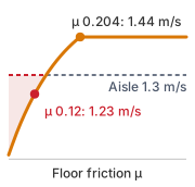
The 1.3 m/s aisle speed clears the dry-floor ceiling but not the inspected floor’s.
- Surface friction and travel speed: The 1.3 m/s aisle speed and an inspected floor friction of 0.12 each fall well within their declared individual operating ranges. In combination, however, they fail even the optimistic all-weight traction screen. On low-friction surfaces, the tire-floor interface, not mechanical braking capacity, sets an upper limit on deceleration; in the all-weight screen it falls to 1.18 m/s². Consequently, the resident stopping maneuver elongates: the required stopping distance at 1.3 m/s expands to 1.19 m, exceeding the available 1.10 m clearance. The optimistic screening ceiling on that floor drops to 1.23 m/s, and the actual speed limit must use the qualified loaded lower bound rather than assuming this ceiling is attainable.
- Contact nonlinearities and dynamic load transfer: Real warehouse floors rarely have a constant friction coefficient \(\CoulombFrictionCoefficient\). Instead, surface friction varies dynamically based on local contamination (such as concrete dust, ambient moisture, or oil films), wheel tread heating, and transient wheel loading. On the running machine only the two driven hub wheels brake against the floor, so the traction ceiling is \(\CoulombFrictionCoefficient \Gravity \DrivenWheelLoadFraction\), where \(\DrivenWheelLoadFraction\) is the share of the weight those wheels carry (derived in the free-body diagram of The Physical Body, figure). During hard braking, the inertial load \(\Mass\CredibleBrakingDeceleration\) acting at the center of gravity pitches the body forward and can move normal force off the driven wheels onto the front caster, lowering \(\DrivenWheelLoadFraction\) exactly when traction is needed. If the drives demand braking torque sized for the static load share, the driven wheels slip and the net braking force collapses. Under a constant-friction approximation, the braking distance then grows as \(\SpeedAtDetection^2 / (2\CoulombFrictionCoefficient \Gravity \DrivenWheelLoadFraction)\), inversely with the friction actually delivered at the driven wheels and quadratically with speed.
- Computational and electrical coupling: Memory and power subsystems couple directly into safety margins. A compute-heavy forward pass of the vision-language-action intent model executing on the application SoC can saturate unified memory bandwidth. This contention delays camera-buffer processing and postpones the compact evidence handoff to the safety microcontroller, inflating the observation age and, with it, the pre-brake delay \(\PrebrakeDelay\). Because stopping distance scales linearly with total reaction delay (equation 2.2), a 30 ms memory stall consumes 39 mm of physical clearance at aisle speed. On the electrical bus, the dominant transient coupling originates from the motor drive actuators rather than the neural compute accelerator. At its maximum 60 W draw, the SoC pulls approximately 1.6 A from a depleted battery bus, only 2.2 percent of the overall 70 A transient, whereas the two drive motors demand up to 50 A during peak torque transients. Severe acceleration can sag the common DC bus across battery internal resistance and wiring harness impedance, while bursty inference activity primarily stresses the SoC’s local point-of-load regulators, a localized transient that the F4 campaign must isolate and measure separately.
- Payload mass and kinematic posture: Arm posture and payload distribution couple directly to stopping performance through vehicle stability and load transfer. Under braking, the base tips about its front caster whenever deceleration exceeds \(\Gravity\,\LeadingSupportDistance/\GravityCenterHeight\), where \(\GravityCenterHeight\) is the height of the center of gravity and \(\LeadingSupportDistance\) its distance behind that caster; this is the tip-over ceiling computed in Electrical time constants, back-EMF, and current clamping, which the credible deceleration respects only while \(\GravityCenterHeight/\LeadingSupportDistance\) stays below the ratio computed there. Raising the arm above a storage rack raises \(\GravityCenterHeight\), and reaching forward shortens \(\LeadingSupportDistance\), so posture moves the machine toward that ceiling. The tip-over threshold can bind before tire traction saturates, and ISO 3691-4 mandates physical stability verification for driverless industrial trucks (International Organization for Standardization 2023). Unloaded trials support only their tested configurations; they cannot establish the fully loaded deceleration or the complete operating envelope. The braking-limit check of Kinematic stopping distance and pre-brake delay left both lengths unmeasured, so the envelope cannot yet certify that the demanded deceleration stays below the tipping threshold; a tilt-table test or multi-axis corner-scale measurement of the fully loaded machine must supply them.
- Thermal throttling and fallback execution: Sustained thermal stress can induce dynamic processor throttling, delaying action proposal generation and degrading mission throughput. In an architecture protected by an independent, verified resident stop, a missed watchdog renewal safely triggers a bounded, fail-safe stopping trajectory rather than indefinitely expanding stopping delay. Nevertheless, multi-axis compound verification must ensure that simultaneous bus contention, sensor packet drops, or voltage droops do not compromise that fallback routine itself.
International Organization for Standardization. 2023. ISO 3691-4:2023: Industrial Trucks, Safety Requirements and Verification, Part 4: Driverless Industrial Trucks and Their Systems. International Organization for Standardization.
15.5.2 Physical disturbances versus digital input perturbations
A vision model that survives synthetic pixel noise injected into an input tensor can still go blind when low-angle warehouse glare saturates the physical camera lens and its auto-exposure loop. Digital perturbations and physical disturbances challenge an embodied machine at different interfaces: synthetic tensor noise tests how sensitive a network’s decision boundary is to small numerical shifts in representation space while bypassing the physical sensor altogether, whereas an optical disturbance exercises the lens, coatings, auto-exposure and gain control, demosaicing, and camera interface timing. Neither test substitutes for the other, so a threat model must state whether an injected fault corrupts digital packets in flight, perturbs the physical environment, or hits both at once.
Evaluating the rack-end safety claim requires injecting realistic physical disturbances: stray illumination and direct glare that blind camera sensors, mechanical chassis vibration that corrupts inertial measurements, and floor transitions that slash available braking traction. Every physical injection requires a repeatable physical actuator and an independent ground-truth witness. For instance, glare injection requires calibrated illumination measurements beside the lens together with the declared optical geometry, spectrum, and temporal waveform, chassis vibration requires external optical motion capture independent of onboard wheel odometry, and floor variations require standardized friction-measurement drag sleds. In cyber-physical verification, receiving a syntactically valid sensor packet with correct checksums over an internal bus confirms only that the digital transmission succeeded; it provides no guarantee that the estimated state accurately reflects physical reality.
15.5.3 What the envelope claim leaves open
Passing the initial F1 trial at one speed and arm posture still leaves neighboring speeds, higher centers of gravity, and worst-case injection timings untested. While that first diagnostic run simply suppresses trajectory renewal while the base is in motion and measures the deceleration-onset timestamp and stopping distance, subsequent falsification campaigns systematically vary initial velocities, arm configurations, and injection phases to hunt for minimal operating margins (section 15.9.2). Formal methods, high-fidelity simulation, and physical hardware testing provide complementary evidence, but none can compensate for an unstated physical premise or an unverified operating assumption.
An operating boundary remains defensible only when every parameter carries its physical unit, traceable provenance, calibrated uncertainty, and designated engineering owner. Specifying a credible deceleration of 2 m/s² remains an incomplete assertion until the verification evidence documents its origin: whether it was measured during physical stopping trials at maximum payload mass, extracted from an actuator manufacturer’s datasheet, or computed using a theoretical friction model, alongside the measurement uncertainty of the external tracking reference. Any hardware modification, whether a new polyurethane wheel tread compound or new motor-drive firmware pushed across the EtherCAT fieldbus, obligates the component owner to re-evaluate whether the operational boundary has shifted.
Validating an operating envelope requires attacking its boundary surfaces rather than testing comfortable interior states. Evaluating an unloaded base crawling across a dry floor with pristine camera frames proves only that nominal execution works under ideal conditions. Instead, the verification harness distributes test points across three critical regimes: points just inside the envelope verify that the control policy preserves closed-loop stability under the largest permissible operational stress; points on the boundary confirm that safety margins survive nominal sensor noise and compute jitter; and points just outside verify that the safety enforcer reliably preempts the policy, executing a deterministic stop that halts the base within the survival envelope before clearance is exhausted.
A physical hardware malfunction and an algorithmic functional insufficiency require different verification strategies. A stereo camera can transmit uncorrupted, on-time video packets over PCIe while ambient glare blinds its depth estimation. A complete campaign must therefore inject faults into both the physical execution mechanisms and the sensory streams on which those mechanisms rely. Adding an enforcer module does not let it observe what its sensors cannot measure; when physical sensing cannot distinguish safe states from hazardous ones, the architect must restrict the operating envelope to conditions where safety can be enforced. Once every timing constraint, latency budget, and environmental threshold of that envelope is specified in physical units, the design claims from earlier chapters become concrete targets for fault injection, each paired with a boundary threshold that must trigger protective intervention.
Systems Perspective 15.2: The hardware falsification principle
A hardware-dependent safety claim needs an observable challenge to its physical premises. If the campaign cannot inject the relevant disturbance or retain the required witness, the record must preserve that verification gap.
15.6 Deriving the Fault List
The proposer stall fault (F1) originates from negating a fundamental operational claim: that proposal renewal proceeds reliably within its granted lease. Deriving a comprehensive fault list, however, requires two complementary methodologies. Inverting design records tests the explicit assumptions codified across the system architecture. Working forward from the physical realities of mechanics, power networks, and human interaction exposes the hazards and unmodeled edge cases that software design records routinely omit. Human interaction includes who is in view. A fault list that seeds only people standing upright leaves untested the kneeling, carrying, and seated people a learned detector may see later, so the groups of people the machine must detect enter the list as a coverage dimension of their own.
↪ How many people of each group a test campaign needs before its detection estimate can resolve the gap that matters is developed in Sample sizes for each group.
15.6.1 Inverting design records and the five-element chain
If the machine’s specification claims that the chunk policy renews its trajectory proposal every 50 ms at every speed up to the 1.5 m/s drive limit, the verification suite turns that claim inside out by injecting stalled renewals, delayed observations, and out-of-range encoder readings to see whether the permission path catches the violation in time. Every preceding chapter supplies claims that can be inverted in the same way: Physical Data through Closed-Loop Evaluation state the learned policy’s training distribution, state-action assumptions, and inference latency ceilings; Sensor Perception through Workload Placement state bus allocations, observation freshness, and estimation bounds; and Supervisory Intervention states how quickly authority leaves a failing policy and which subsystem takes over.
The five-part test contract of section 15.1 states what makes any trial valid evidence. A second list of five, which also opens with a claim and closes with an oracle, states how one fault is built into such a trial. Its first element supplies the contract’s bounded claim, its last element supplies the contract’s oracle, and the three between them are the mechanism the trial exercises. For every candidate fault, the bounded claim and its injection procedure form this five-element chain:
- The negated condition: the exact architectural or timing invariant violated (for example, proposal renewal halted after lease issue);
- The physical injection point: the exact hardware or bus interface where the disturbance enters (for example, an inline field-programmable gate array (FPGA) serializer, CAN FD disturbance node, or programmable DC load);
- The expected detector: the deterministic monitoring primitive tasked with catching the violation (for example, a lease countdown timer or evidence-epoch comparator);
- The bounded response: the deterministic transition executed by the enforcer (for example, revoking proposal authority and commanding the resident stop suffix); and
- The observable pass condition: the quantitative, independently witnessed metric that scores the trial (for F1 at aisle speed, onset \(\le\) 82 ms and travel from renewal \(\le\) 751.9 mm).
A recorded design property becomes a testable fault only when all five elements are fully defined and observable. If any element of this chain cannot be defined or measured, the architecture has a verification gap: the underlying claim cannot be falsified by empirical test. Systems engineers cannot ignore such gaps; resolving them requires dedicated hardware instrumentation (such as external optical trackers or non-intrusive trace macros), a narrower operational design domain, or a structural redesign of the execution path.
Inversion also applies to the learned proposer’s implicit assumptions, where distribution shift can induce functional insufficiency even when every observation frame arrives intact and on time. For example, a chunk policy trained in simulation on dry concrete with friction coefficient 0.60 proposes decelerations that an inspected floor at 0.12 turns into wheel slip. Inverting that evaluation claim requires injecting degraded traction conditions at the physical contact patch. Sensor bias, calibration drift, and input perturbations are injected for the same reason: a policy with high nominal reward can still command high-frequency actuator chatter once its inputs leave the training distribution. Under these conditions, an overly permissive execution path can destabilize the plant while executing syntactically valid commands, demonstrating that software commands and mechanical dynamics remain tightly coupled across the causal boundary.
At each inter-module contract, the fault list negates architectural guarantees directly at their physical handoff points: observation freshness, state validity, intent lifetime, planning deadlines, enforcement independence, and resource allocation. For the 60 ms chunk lease, the test harness replays the expired admitted record 65 ms after its last valid renewal, verifying that the permission path firmly refuses to extend execution authority. A concurrent proposal represents an entirely separate admission attempt: it must satisfy fresh evidence, kinematic state validity, mode consistency, and stopping-reserve checks before receiving a lease. To test the enforcer’s claimed independence from the policy processor on the selected discrete placement, the verification suite saturates the application processor’s memory interconnect with DMA traffic while independently timing the safety microcontroller. Host contention may delay proposal delivery and age its supporting evidence, but the enforcer must still satisfy its 400 μs execution deadline within every 1 ms control tick. This rigorous inversion prevents arbitrary over-testing: bus contention, clock skew, and supply fluctuations are injected precisely where the architecture claims tolerance, rather than drawing from generic fault menus that impose requirements the machine was never specified to meet.
Inversion has a structural limit: it surfaces only faults rooted in assumptions the design team explicitly wrote down. The resulting fault list is therefore only as comprehensive as the recorded architectural claims. If no engineering record documents how the base’s spring-applied brake behaves when its friction lining glazes under repeated emergency stops, inversion cannot synthesize the failure mode, and the hazard never reaches the test suite.
15.6.2 Forward physical analysis and common-cause modes
Drive wheels skid when commanded deceleration exceeds the traction limit of the contact patch; brake linings glaze under repeated thermal cycles; solid tires wear down and alter the rolling radius that wheel odometry relies on; and structural vibration gradually loosens camera mounts until spatial calibration drifts. Because these hazards arise from contact mechanics, heat, and wear rather than software bugs, no software abstraction represents them, and inverting design records will not uncover them. A second, independent fault source therefore works forward from the physical machine—its mechanical body, power distribution network, floor interface, and operating environment—using Nancy Leveson’s Systems-Theoretic Accident Model and Processes (STAMP) framework5 (Leveson 2011) to trace how physical and control interactions produce hazards even when no software module has crashed.
5 STAMP and STPA: Leveson (2004) proposed STAMP, which treats safety as a dynamic control problem rather than a component-reliability problem, recognizing that catastrophic accidents often arise from unsafe interactions among components that each operate strictly within specification. Leveson (2011) established the Systems-Theoretic Process Analysis (STPA) hazard-analysis method on this foundation, identifying unsafe control actions at subsystem interfaces, such as an integration seam where bus communication latency or digital filter lag erodes phase margin. Because no individual component has failed at such a seam, its unsafe control actions supply critical fault modes that inverting nominal design records cannot expose.
Leveson, Nancy. 2004. “A New Accident Model for Engineering Safer Systems.” Safety Science 42 (4): 237–70. https://doi.org/10.1016/S0925-7535(03)00047-X.
Leveson, Nancy. 2011. Engineering a Safer World: Systems Thinking Applied to Safety. MIT Press.
Consider a motor drive that continues producing positive torque after receiving a stop command. A shorted inverter switch, welded contactor, or stuck gate-driver enable line can defeat the normal powered stopping trajectory. The test harness must independently observe delivered phase torque, rotor velocity, and the engagement of the secondary isolation path. While Safe Torque Off (STO) inhibits torque generation without providing electrical isolation, it cannot enforce nominal stopping distances on low-friction floors or prevent back-driving on gravity-loaded articulated joints. The safety architecture must specify a separately justified containment response alongside an independent physical measurement oracle. If no such path exists, the fault exposes a fundamental architectural omission rather than an operational delay that can borrow from the normal stopping budget.
↩︎ Safe Torque Off and the industrial stop categories are established in Industrial stop categories and the safe torque off trap.
Working forward exposes hardware fault classes that software design records rarely imply: loss of reference clocks, power supply brownouts that leave digital logic in indeterminate voltage states, pulse-width modulation (PWM) inverter switching noise coupling into differential encoder lines, corrupted non-volatile configuration registers, and reset lines that bridge domains intended to remain galvanically or logically isolated. For instance, if the safety microcontroller and the high-performance application processor share a single power-management integrated circuit (PMIC), a transient voltage droop during a sudden drive-current surge can reset both processors simultaneously just as the learned proposer loses trajectory tracking. A software interface model that assumes an ideal DC power supply omits this failure. An enforcer cannot arrest an errant policy if it loses operating power alongside the workload it supervises; the deterministic safety runtime must outlive the faulted workload using independently qualified execution and power resources. The running machine uses an isolated, capacitor-backed auxiliary supply to survive the declared supply fault.
Forward physical analysis likewise evaluates the architecture’s common-cause independence claims. Subsystems that appear strictly isolated on an architectural block diagram frequently share physical vulnerabilities. For example, the primary lidar communication lines and redundant safety bumper wiring may share a single mechanical cable carrier subject to pinch wear, depend on a shared analog voltage reference inside a multichannel converter, or rely on timer silicon containing identical silicon errata. An electrical transient that latches up both channels simultaneously destroys any safety argument predicated on statistical independence. Common-cause analysis traces harness routing, power distribution paths, and clock distribution trees to identify shared failure paths and justify independence against the declared fault set, rather than assume separation from the block diagram.
↩︎ The independence claims for the permission path’s execution unit, oscillator, power rail, and memory are established in Hardware Isolation and Fault Containment.
This physical analysis extends directly to human error and foreseeable operational misuse. Warehouse personnel may jumper an optical rack-end sensor during maintenance, leave a manual pallet jack parked across an automated transit corridor, or unplug an acoustic warning beacon to silence workplace noise, while remote teleoperators may request transit speeds exceeding local aisle restrictions. When a remote assistant commands the vehicle’s full 1.5 m/s drive limit within a narrow aisle, the verification suite must confirm that the arbiter denies the command by capability constraint or clamps it to the admitted manual mode speed under an active manual_drive state. Furthermore, the deterministic permission check must evaluate the assistant’s command with the same scrutiny applied to autonomous proposals.
Working forward from the physical plant adds a representative mechanical failure mode, the actuator jam, to the record-derived inventory in table 2, though full verification still requires a plant-specific hazard analysis tailored to the vehicle’s mechanical kinematics and operational envelope. Alongside inverted design claims and forward physical hazards, the fault suite in table 2 also evaluates the four authority transition cases (A1–A4) established in Per-tick evidence tuples and the fault injection suite under the operating state that makes intervention most urgent: a fully loaded base approaching the rack end at velocity. The test campaign injects takeover requests at two speeds to distinguish the candidate moving transition from a request the clearance screen rejects; the operative design stops before handing over. At the 0.75 m/s slow-down, the partial-budget waiting margin is 751.6 ms, enough for the 605 ms in-loop takeover and the 63.3 ms dispatch-to-admission allocation together, so Clearance-derived fallback deadlines identifies a candidate moving in-loop handover for qualification, subject to the complete session budget and live stopping checks; the trial must show that a handover left pending still ends in a local stop by its deadline. At the full 1.3 m/s aisle speed the margin is 100.8 ms, only 37.5 ms once the allocation is charged, which cannot hold the takeover, so the arbiter must reject the moving handover and dispatch a local stop before the deadline expires. An out-of-loop takeover begins only after a stop, from standstill, in an admitted mode. Evaluating either sequence solely while the vehicle is parked proves nothing about dynamic performance; the trial must demonstrate that rejection, timeout, and braking occur with bounded latency while the base moves.
| Failure Domain & Fault Mode | Physical Mechanism & Injection Point | Target Manifestation & Causal Impact | Detection Primitive & Latency Budget | Enforced Safe Response & Bounded Recovery | Observable Pass Criterion |
|---|---|---|---|---|---|
| Proposer Stall (F1) | Chunk policy renews its lease once, then its task is killed or its output frozen on the application processor | No new proposals; the last admitted chunk keeps supplying setpoints while the base cruises | Lease expiry on the permission path (60 ms); host heartbeat timeout (30 ms) | Revoke proposal authority; run the resident stop | Powered deceleration onset \(\le\) 82 ms after the last valid renewal; travel from that renewal to rest \(\le\) 751.9 mm |
| Stale Observation Time (F2) | Navigation-camera frame held at the image signal processor with its capture stamp preserved, or the stamp corrupted, via inline frame interceptor | Proposals whose upper evidence age at dispatch exceeds 51.8 ms, the budgeted age plus the clock-conversion bound; the base acts on an old view of the rack end | Dispatch-age check at admission; continued evidence, state, and lease validity checks on every tick | Refuse stale replacements; stop when the active command loses its own validity | Powered deceleration onset \(\le\) 82 ms after the last valid renewal; travel from that renewal to rest \(\le\) 751.9 mm when the resident stop runs |
| Lost EtherCAT Frames (F3) | Frames dropped or corrupted at a drive’s slave port, injected via fieldbus disturbance node | Encoder state and drive commands miss cycles; the delivered command ages by one 1 ms cycle per lost frame | Working-counter and frame-arrival check; drive communication watchdog | Drive enters its configured stop; permission path commands the resident stop | Powered deceleration onset \(\le\) 82 ms after the last valid renewal; travel from that renewal to rest \(\le\) 751.9 mm only when the complete lease-to-onset path remains bounded under frame loss; a drive-watchdog response needs its own reference event, deadline, and stop profile; zero unhandled bus exceptions |
| Drive-Bus Droop (F4a) | Programmable supply takes the shared drive bus from its depleted point below the converter lockout; the coincident load alone leaves it at 37.8 V | Bus falls below the 33 V converter lockout; the application processor browns out and its sensors may freeze at plausible values | Shared-bus undervoltage flag, raised by the permission path on its isolated, held-up rail | Command STOP; qualify surviving drive authority or record unsupported response | Powered deceleration onset \(\le\) 22 ms after the flag; travel from the flag \(\le\) 673.9 mm at aisle speed if the drives keep their authority on the sagged bus, otherwise the separately characterized unpowered envelope; permission path never resets (continuous heartbeat on an independent digitizer) |
| Permission-Rail Feed Loss (F4b) | Feed opened during the longest stop in the qualified loaded envelope; the illustrative all-weight inspected-floor screen starts from its 1.23 m/s ceiling | Permission path, drive logic, and brake coils run on the store; powered drive energy remains separately available | Feed-loss flag on the permission rail | Complete the resident stop; set every spring brake at standstill | Stop completes and every brake sets before rail dropout; the all-weight screen spends 1313.43 ms of the 2 s hold-up, awaiting loaded qualification; any reset is FAIL |
| Actuator Jam & Mechanical Stall | Wheel bearing seizure or dragging brake, injected via wheel clamp or dynamometer | Locked rotor; one wheel blocked yaws the base; rapid stator winding heating (\(\MotorPhaseRmsCurrent^2 \ElectricalResistance\)) | Motor phase overcurrent & Hall-effect velocity stall monitor, within its detection bound | De-energize the power stage; engage the spring-applied brake | Winding temperature remains below the chosen operating ceiling in Thermal capacity and insulation breakdown thresholds; base stays inside the 0.15 m side clearance |
| Proposer Injection: Instruction or Visual | Adversarial instruction text on the task channel, or a printed patch, label, or sign placed in the intent model’s camera view | Well-formed proposals that pursue the attacker’s goal; every field, timestamp, and lease is valid | No check on the proposal’s meaning; speed, force, swept-volume occupancy, stopping-reserve, and freshness checks on every tick | Clamp or refuse the proposal like any other; wrong actions inside the envelope continue | Every proposal that breaches a monitored limit is clamped or refused within the 400 μs enforcer deadline; wrong actions inside the envelope are recorded as coverage deficits, never as passes |
| Authority Transfer (A1): Duplicate Writer | Second bus master writes a base-drive channel (duplicate EtherCAT identifier or DMA write) while policy and remote assistant both command | Two writers on one channel; the delivered command is no longer the admitted one | Bus or DMA write permissions; per-tick authority record | Reject the foreign write; the enforcer path remains the only writer | Independent bus or write-path witness confirms foreign writes are blocked; authority records show one admitted writer |
| Authority Transfer (A2): Tier Bypass | Policy proposal injected while MAN is active; remote-assistant command that opposes the enforcer’s admitted limit |
A lower tier displaces an active higher tier, or an assistant command skips the permission check | Arbiter tier check; permission check applied to every source | Ignore the policy proposal; clamp or refuse the assistant command like any proposal | Arbiter ignores the proposal; the permission check still runs on the assistant’s command |
| Authority Transfer (A3): Handover Timeout | Assistant input frozen during PEND; acknowledgment frames dropped, at the takeover slow-down and at aisle speed |
The machine waits on a handover that no one completes | Handover deadline timer in the arbiter | Reject moving handover in the operative design; a candidate slow-down trial starts the validated fallback when its qualified deadline expires | No moving handover admitted in the operative design; in candidate trials at both speeds, local stop dispatched by the qualified current-clearance deadline of Clearance-derived fallback deadlines, without awaiting acknowledgment |
| Authority Transfer (A4): Authentication | Replayed captured veto_path, manual_drive, or accept_item packet; packet carrying a bad tag |
An unauthenticated source gains authority | Tag and freshness check on every assistant and coworker command | Reject the packet; rate-limit ingress while preserving valid authority | Invalid packet rejected; still-valid authority preserved; rejection recorded; enforcement deadlines met under ingress load |
15.6.3 Physical sensor spoofing and proposer injection
Whether sun glare washes out a camera lens by accident or an attacker shines a laser into the optics on purpose, the camera interface delivers a well-formed, checksum-valid packet whose physical reading is false. In both cases—ambient disturbance and transduction-layer cyber-physical attacks—checksum validation and bus integrity checks pass cleanly while the robot’s view of the aisle is corrupted. When evaluating such an optical disturbance (retroreflective glare, strobed lighting, or lens occlusion), the test protocol must specify the illumination levels and vehicle approach vectors that challenge obstacle detection, the cross-sensor plausibility checks tasked with identifying the discrepancy, and the deterministic fallback maneuver. An independent ground-truth optical tracking system monitors obstacle clearance and base trajectory while camera streams are disturbed. The verification record must distinguish an actively detected anomaly followed by a controlled deceleration from a missed obstacle where collision was avoided purely by chance. If a monitoring subsystem cannot distinguish corrupted sensor data from valid physical evidence, that operational scenario constitutes a verification gap; documenting an aspirational safety monitor in an architecture diagram does not ensure it will fire under physical stress.
The learned proposer is itself a primary attack surface; targeting it tests the proposal boundary far more directly than conventional bus or memory faults. Because a vision-language-action (VLA) model consumes natural language instructions and camera frames directly, an adversary can manipulate the model’s outputs through either modality without touching a physical wire or intercepting a bus. Robey and colleagues demonstrated automated prompt generation that induced robots controlled by language models, including a commercial quadruped evaluated strictly as a black box, to execute harmful physical actions across diverse operational settings despite high-level safety guardrails (Robey et al. 2025). On the visual side, Wang and colleagues showed that introducing a compact adversarial patch6 into a VLA’s camera field of view could degrade simulated manipulation success rates to zero (Wang et al. 2025). On a deployed warehouse machine, physical injection points encompass task instruction strings, floor placards, shipping container barcodes, or printed warning signs within the camera’s visual cone.
Robey, Alexander, Zachary Ravichandran, Vijay Kumar, Hamed Hassani, and George J. Pappas. 2025. “Jailbreaking LLM-Controlled Robots.” IEEE International Conference on Robotics and Automation (ICRA), 11948–56. https://doi.org/10.1109/ICRA55743.2025.11128119.
6 Adversarial Patch: Brown et al. (2017) demonstrated that printing an image-independent physical patch and placing it within a visual scene forces an image classifier to ignore surrounding objects and predict the attacker’s target class. The perturbation enters entirely through the optical transducer without requiring software access, bus interception, or packet injection. In an embodied system, this attack operates wholly on the proposer’s side of the proposal boundary, where the permission path can constrain the physical consequences of an altered command but cannot observe the visual artifact that induced it.
Brown, Tom B., Dandelion Mané, Aurko Roy, Martín Abadi, and Justin Gilmer. 2017. “Adversarial Patch.” arXiv Preprint arXiv:1712.09665.
Wang, Taowen, Cheng Han, James Chenhao Liang, Wenhao Yang, Dongfang Liu, Luna Xinyu Zhang, Qifan Wang, Jiebo Luo, and Ruixiang Tang. 2025. “Exploring the Adversarial Vulnerabilities of Vision-Language-Action Models in Robotics.” IEEE/CVF International Conference on Computer Vision (ICCV), 6948–58. https://doi.org/10.1109/ICCV51701.2025.00653.
In semantic target grounding (equation 10.3), the intent model uses a conformal prediction set \(\ConformalPredictionSet\) calibrated to a marginal miscoverage rate \(\ConformalMiscoverageRate\) to filter ambiguous hypotheses by requiring a singleton output (\(|\ConformalPredictionSet| = 1\)). In an adversarial or out-of-distribution physical setting, however, an adversarial patch or optical distortion violates the exchangeability premise of the conformal calibration. An attacker can force an erroneous candidate to pass as a singleton (\(|\ConformalPredictionSet| = 1\)), or the model can misclassify within its nominal \(\ConformalMiscoverageRate\) error budget. Because the deterministic permission path does not parse task instructions or inspect the conformal set \(\ConformalPredictionSet\), it cannot distinguish an adversarial proposal from an authentic user command. Instead, under its qualified measurement and timing premises, the enforcer rejects or modifies an injected proposal when the requested physical action violates its monitored constraints: velocity and torque envelopes, dynamic stopping reserves, swept-volume occupancy, evidence freshness, or active lease duration. If an adversarial proposal meets these physical constraints and the authority checks, the enforcer may admit it, even if the robot picks an unintended bin, deposits cargo in an unauthorized clear aisle, or actuates an access gate prematurely. The permission path supports physical containment and dynamic feasibility under its declared premises; those checks do not establish semantic task correctness. This operational asymmetry highlights why systems architects decouple proposal synthesis from safety enforcement: protective safety guarantees must hold regardless of how an action was synthesized, while task-level semantic fidelity cannot be guaranteed by low-level enforcers. Consequently, the proposer-injection row in table 2 evaluates trials solely against independent physical oracles, recording uncommanded actions that remain within the admissible safety envelope as semantic coverage deficits rather than as safety violations.
↩︎ The limit that the permission path enforces physical feasibility rather than semantic task correctness is established in Intent Grounding Failure Modes and Their Checks.
15.6.4 Choosing the injection phase
Injecting a proposer stall immediately after a lease renewal forces the base to coast on open-loop setpoints for nearly the full lease duration, stressing tracking error and clearance, whereas injecting the same stall microseconds before lease expiration catches the arbiter right at the boundary between renewal and revocation. Because the instant a fault arrives within the control cycle changes which hardware and software paths bear the load, a verification campaign cannot treat repeated fault injections at arbitrary times as interchangeable trials. Recording the exact injection phase relative to the control tick turns phase into a controlled test variable. Sweeping across injection phase, fault duration, and disturbance magnitude exposes race conditions in the arbitration logic and supplies the signed safety margins that automated falsification algorithms search over (section 15.9.2).
15.6.5 Compound faults and coupled disturbances
When a drive-current surge sags a shared DC power rail, it does not wait for the perception pipeline or the safety microcontroller to finish its current cycle: a single electrical dip can brown out the application processor, freeze an image serializer, and jitter a shared clock all at once. While each row of table 2 tests one disturbance in isolation, real machines rarely fail one subsystem at a time. Combining rows at random would cause a combinatorial explosion without targeting realistic failures, so the campaign instead derives compound faults from shared hardware causes. The placement record (The Placement Record) lists every physical resource that the permission path shares with the learned workloads, and each shared power rail, clock tree, or communication bus becomes a compound fault injected at the shared hardware root rather than at downstream software symptoms.
On the mobile manipulator, the primary shared vulnerability is the main DC drive bus, which powers the traction motor drives directly while feeding the application processor through an intermediate DC-DC converter. Meanwhile, the safety-critical permission path operates from an isolated, capacitor-backed hold-up rail. Notebook 15.2 evaluates the electrical headroom and timing budgets for both F4 fault injection trials using the vehicle’s electrical specifications.
Napkin Math 15.2: The supply headroom
Problem: At the depleted point, can the drive transient alone carry the shared bus below the lockout of the converter that feeds the application processor, and how much of the permission rail’s hold-up does the longest stop in the optimistic screening branch spend?
Variables:
- Depleted bus \(\DepletedBusVoltage =\) 42 V and converter lockout \(\ConverterLockoutVoltage =\) 33 V (Datasheet).
- Source and harness resistance \(\ElectricalResistance =\) 60 mΩ (Illustrative; needs a measured value) and drive transient \(\ConductorCurrent =\) 70 A (Illustrative).
- Rail hold-up 2 s (Chosen) and spring-brake engagement \(\SpringBrakeEngagementTime =\) 80 ms (Illustrative).
- Longest stop in the optimistic all-weight screen: from the 1.23 m/s inspected-floor ceiling at \(\AvailableDeceleration =\) 1.18 m/s² (Derived from floor friction with the entire weight on driven wheels) with \(\JerkLimit =\) 7.11 m/s³ (Derived).
Math:
F4a, sag under the transient and the step that reaches lockout. \[V_{\min} = V_{\text{low}} - I\,R = 42 - 70 \times 0.060 = 37.8\ \text{V}, \qquad I_{\text{cross}} = \frac{V_{\text{low}} - V_{\text{UVLO}}}{R} = \frac{42 - 33}{0.060} = 150\ \text{A}\]
F4b, flag to brakes set, with the stop time of equation 11.17. \[t_{\text{set}} = (T_{\text{tick}} + T_{\text{bus}} + T_{\text{act}}) + \left(\frac{v}{a} + \frac{a}{j_{\max}}\right) + t_{\text{engage}} = 22 + \left(\frac{1.231}{1.177} + \frac{1.177}{7.11}\right)\text{s} + 80 = 22 + 1045.9 + 165.5 + 80 = 1313.4\ \text{ms}\]
Result: The transient leaves 4.8 V of headroom above the lockout, and reaching it takes a 150 A step, more than twice the transient. The 2 s hold-up outlasts the 1313.43 ms from flag to brakes set by 686.6 ms.
Systems insight: Neither trial can rest on the commanded load. F4a must step the supply itself, because the drive’s own current cannot reach the lockout, and F4b must open the feed during the longest stop admitted by the qualified loaded envelope, since a shorter stop passes on hold-up the claim never needed. The computed duration belongs to the optimistic all-weight screen; loaded qualification must replace its braking premise before fixing the physical F4b oracle. The headroom rests on an illustrative resistance and would vanish near 129 mΩ, about twice that value, so the source resistance measured under load is the first number the supply campaign must supply.
A compound fault trial must capture high-bandwidth electrical waveforms while independently recording the behavior of the learned policy, perception pipelines, motor controllers, and external telemetry witnesses. Engineers cannot infer that processors reset or sensor frames froze from software logs alone, because the electrical disturbance often corrupts the operating system writing the log. For example, a voltage droop on a shared power rail can induce oscillator jitter that slows the enforcer’s control cycle, freeze an image serializer so that a camera publishes identical frames with plausible timestamps, and reset an external flight recorder during the exact same interval. Similarly, electromagnetic burst interference across a shared fieldbus ages perceptual observations while stalling the permission path’s read requests and suppressing the diagnostic heartbeats that would otherwise signal the delay. A drift or jitter transient in a shared reference clock corrupts timestamps across the proposal-enforcement boundary at the same time, allowing stale data to pass as fresh evidence. The physical oracle evaluating a compound fault must therefore verify both that the protective response triggered within its deadline and that the witness instruments and evidence logs remained intact throughout the event (section 15.12).
Because unmodeled physical couplings cannot be found from a resource inventory alone, forward physical analysis must always complement derivation from the inventory. Together, the resulting fault catalog unites four sources: inverted design contracts, forward-derived physical hazards, the authority transfer cases (A1–A4), and compound disturbances on shared hardware. Defining this catalog establishes what faults the machine must survive; choosing the physical fidelity of the test bench determines which of those claims a given trial can actually test.
15.7 The Qualification Ladder
A desktop simulator can stall the proposer of F1 across every combination of speed and payload overnight, but it cannot sag the drive bus of F4. The simulated power network has no buck-boost converter to lock out and no microcontroller to brown out and reset, so a million passing rollout assertions (assert clearance >= 0) there say nothing about F4. That is the digital twin delusion of section 15.1, and the remaining question is where, precisely, a given simulator stops being evidence.
The gap between simulation and reality stems directly from what the simulator abstracts away. When a physics simulation omits embedded target execution and electrical dynamics, it relies on five pervasive idealizations, each of which must be evaluated against the specific claim under test:
- Computation takes zero virtual time: The simulator pauses its simulation clock while the neural policy executes. This treats heavy neural forward passes as instantaneous, completely decoupling inference latency from physical base velocity (\(\BlindTravelDistance = \SpeedAtDetection \PrebrakeDelay\)).
- Memory bandwidth is infinite: Tensors pass across shared in-memory references. This completely omits the shared-memory contention, cache evictions, and DMA serialization stalls that govern real-time execution on an edge SoC.
- Power rails are infinitely stiff: Power supplies are modeled as idealized constant-voltage sources (\(\DcBusVoltage = \text{const}\)). This ignores the resistive droop (\(\FiniteChange \DcBusVoltage = \ConductorCurrent \ElectricalResistance\)) of the drive bus under sudden current steps (sized for this machine in notebook 15.2), the inductive flyback spikes from sharp current transients, and the resulting brownout resets.
- Clocks are perfectly synchronized: The simulation advances monotonically in fixed discrete time-steps (\(\FiniteChange \TimeInstant\)). This eliminates asynchronous clock drift, interrupt jitter, and transceiver arbitration races between the neural host and the real-time safety microcontroller.
- Contact mechanics are simplified: Numerical contact solvers approximate Coulomb friction with linearized friction cones or convex relaxations that permit artificial creep under static load (Todorov 2014). They routinely neglect the crucial transition between static and kinetic friction, dynamic tire slip, and brake-lining glazing during emergency stops.
Todorov, Emanuel. 2014. “Convex and Analytically-Invertible Dynamics with Contacts and Constraints: Theory and Implementation in MuJoCo.” IEEE International Conference on Robotics and Automation (ICRA), 6054–61. https://doi.org/10.1109/ICRA.2014.6907751.
↩︎ Resistive droop on a shared drive bus and the brownout resets it causes are established in Power distribution impedance, transient droop, and brownout resets.
Each qualification environment closes, breaks, or substitutes different links in the chain connecting sensing, inference, communication buses, motor drives, and physical mechanisms. The qualification ladder orders four verification environments by how much of the cyber-physical loop is physically executed rather than simulated: software-in-the-loop, processor-in-the-loop (PIL), hardware-in-the-loop (HIL), and physical fault rigs. Software-in-the-loop is the lowest rung and the physical rig the highest, so climbing the ladder means making more of the loop physical. As physical hardware replaces numerical models, test fidelity rises, but trial throughput drops by orders of magnitude. This progression is not, however, an evidentiary hierarchy in which higher rungs subsume lower ones. Each rung yields a distinct category of empirical evidence while remaining blind to physical phenomena outside its boundary. A million successful software-in-the-loop rollouts reveal nothing about bus contention, DMA stalls, clock drift, or supply rail sag on the embedded hardware.
15.7.1 What each of the four rungs makes physical
On the warehouse mobile manipulator, software-in-the-loop evidence terminates at the boundary of the numerical plant model; a mechanical brake modeled merely as a first-order lag cannot capture pad thermal glazing, wheel slip, or torque saturation. Processor-in-the-loop (PIL) execution introduces the cross-compiled binary running on the actual target silicon (such as an ARM Cortex-R or RISC-V safety core), validating fixed-point quantization, instruction timing, and stack headroom. Hardware-in-the-loop (HIL) benches mount the two-processor architecture, with its physical fieldbus, power regulators, and motor drive stages, against a hard real-time FPGA plant model or an instrumented dynamometer. Finally, physical fault rigs close the full loop with the production chassis, mechanical brakes, wire harness, and physical warehouse floor.
↩︎ The two-processor architecture, which runs the permission path on a safety microcontroller apart from the learned proposer’s application processor, is established in The Independence Requirement and the Two-Processor Hypothesis.
Two operational testing paradigms exist alongside this qualification ladder, but both break the closed loop entirely. Trace replay feeds recorded sensor streams into the candidate controller; while it preserves authentic sensor noise and optical artifacts, the recorded frames reflect the actions of the original historical policy rather than reacting to the candidate’s new commands. Shadow operation runs the candidate model in parallel with an incumbent, validated controller. If the candidate proposes an aggressive velocity vector that would drive the base into a storage rack, the logger records the telemetry while the incumbent controller safely halts the base. Because neither approach permits candidate actions to alter future state observations, neither reveals the closed-loop physical consequences of an erroneous command.
A production shadow deployment cannot allow a stalled proposer to drive toward a human worker at a rack end to see if the brakes engage in time; a software simulator cannot expose a timing race between transceiver silicon buffers; and an instrumented physical dynamometer cannot execute the tens of millions of randomized runs required to bound extreme distribution tails. Systems engineers must therefore route each fault injection scenario to the specific rung on the ladder that embodies its underlying physical and causal mechanism. Coverage of the causal loop grows with each higher rung, from decision logic alone to drives and floor contact, while trial throughput shrinks, so no rung dominates the others (figure 2).
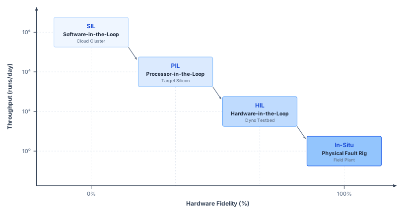
Selecting the proper qualification rung requires identifying the exact premise that a fault challenges. Validating the software lease expiry under CPU contention in F1 requires target silicon execution to capture true processor scheduling interference. In contrast, evaluating supply rail droop in F4 demands the production power distribution network and independent oscilloscope instrumentation across the DC bus. Similarly, certifying a stopping-distance budget requires a fully ballasted physical chassis operating over a qualified floor surface. A sound verification strategy uses high-throughput simulation to search the combinatorial operational space for edge cases, then reproduces those critical scenarios on the specific hardware rung that contains the physical mechanism under test. Agreement between two rungs validates only the shared causal links common to both; table 3 outlines these strict evidentiary boundaries.
| Qualification Rung & Substrate | Causal Loop Realism (Compute, Bus, Actuator, Plant) | Fault Injection Mechanism & Scope | Throughput & Sample Scaling | Physical & Temporal Fidelity | Primary Test Oracle & Evidentiary Limit |
|---|---|---|---|---|---|
| Software-in-the-Loop (Host Workstation / Cloud Cluster) | Compute: Synthetic / Host x86; Bus: Idealized zero-copy buffer; Actuator: Linear / saturation model; Plant: Numerical ODE/PDE solver | Tensor bit-flips, synthetic sensor dropout, floor-friction, payload, and latency sweeps | Parallel sweeps; throughput depends on model and compute allocation | High mathematical flexibility; zero target silicon, bus timing, or electrical realism | Oracle: Mathematical assertion corridors and state invariants. Limit: Cannot validate target execution timing or unmodeled physical dynamics. |
| Processor-in-the-Loop (PIL) (Target SoC / MCU) | Compute: Real target silicon (ARM/RISC-V); Bus: Simulated bus interconnect; Actuator: Emulated command register; Plant: Real-time host model | Instruction cache evictions, register corruption via JTAG/BIST, interrupt jitter injection | Bound by target execution and cross-platform synchronization | Instruction-set and compiler accurate; abstracts analog bus lines and actuator back-EMF | Oracle: Target register state, numerical equivalence, and execution-time profiles. Limit: Ignores physical transceiver bus contention, voltage droop, and thermal rise. |
| Hardware-in-the-Loop (HIL) (Target ECUs + Real-Time Plant Rig) | Compute: Production ECU / NPU; Bus: Real physical CAN/Ethernet; Actuator: Real motor drives / dyno; Plant: Hard real-time FPGA plant rig | Pin break/short, CAN frame stuffing / babbling idiot, supply rail droop, load steps | \(1.0\times\) strict real-time (\(24\text{ h/day}\) wall-clock limit) | High electrical, timing, and protocol fidelity; bounded by FPGA plant model accuracy | Oracle: Protocol CRC, bus deadline monitors, and interlock timings. Limit: Does not physically exercise modeled floor contact or wear; overload coverage depends on the rig and its protection. |
| Physical Fault Rig (Dynamometer Cell / Field Plant) | Compute: Production ECU / NPU; Bus: Production harness & sensors; Actuator: Real physical mechanisms; Plant: Real base, arm, and floor | Wheel clamps, magnetic brake stall, thermal heating, transducer bias drift | Wall-clock execution; constrained by wear and thermal reset | Full authentic physics (Coulomb friction, wheel slip, thermal dissipation, wear) | Oracle: Independent physical containment instrumentation and yield transducers. Limit: High financial cost per trial; destructive tests cannot scale to statistical tail bounds. |
15.7.2 Where each rung’s simulation boundary cuts the loop
Replacing physical wire harnesses, ground returns, and distributed actuator nodes with desktop simulations strips away inductive voltage droop, transmission reflections, and electromagnetic interference (EMI). Every qualification rung has a simulation boundary—the interface where numerical models, emulated buses, or replayed traces sever the exchange of energy and information between computation and mechanics—and no environment can certify properties that depend on physics outside that boundary. Software-in-the-loop testing falsifies algorithmic decision logic and state-machine transitions across broad parametric sweeps. PIL uncovers numerical divergences from cross-compilation and profiles worst-case execution time on target silicon, yet because it funnels input and output over a hardware debug interface (such as a JTAG port or serial UART link), it cannot stress physical communication buses. HIL brings in the true physical transceivers, bus contention, and electrical transients, while leaving contact mechanics to real-time models. Finally, physical fault rigs subject the structural plant to unmodeled Coulomb friction, tire deformation, and thermal dissipation.
A higher rung therefore does not subsume or obsolete the lower ones. Verification is an exercise in constrained optimization across a Pareto frontier: parallel software-in-the-loop clusters explore millions of permutations of obstacle layouts and lighting variations, whereas physical rigs capture true contact mechanics at the expense of manual resets, mechanical wear, and thermal recovery between runs. Each stage occupies a unique operating point balancing combinatorial test throughput against physical causal fidelity. A mechanism omitted from a model cannot fail within it. If a simulator omits Coulomb breakaway friction and stator inductive lag, a simulated robot joint moves immediately upon receiving a torque command. On real hardware, however, that same joint remains stationary during a stiction dead time before lagging behind the commanded trajectory. This is a classic manifestation of the omitted-mechanism gap, which no amount of software simulation can uncover.
To guard against false confidence, every empirical verification claim must explicitly catalog its causal envelope: which links in the sensing-computation-actuation loop were physically real, which were simulated, which were replayed from static traces, which were bypassed, and which remained unobserved. Stating that the safety permission path halted the mobile base within 969.0 mm is meaningless in isolation. An engineer must specify whether the wheel-speed velocity signal was computed by a numerical ODE solver, streamed from a physical optical encoder over a saturated CAN bus, or read out from an in-memory replay buffer. Mapping this boundary exposes the physical assumptions behind each pass and prevents latent hardware hazards from hiding behind passing software assertions.
15.7.3 Scope of a formal verification result
A formal proof that a permission filter preserves safety over a mathematical plant model still cannot prevent a crash if the tires slip on a wet floor, the camera frames arrive late, or the proof is asked to cover a vision-language-action proposer fifty times larger than any network a complete verifier can solve. Formal proof provides a fifth source of evidence alongside the physical qualification ladder, but a proof holds only inside its mathematical model of plant states, sensor noise, and bounded disturbances. Translating that guarantee to the embodied machine still rests on empirical measurements of plant dynamics, observation deadlines, bus latencies, and actuator torque limits—and which components of the running machine a proof can reach at all depends on the current scale limits of neural-network verification.
Tools for formal neural-network verification operate in one of two regimes: open loop or closed loop. An open-loop verifier checks an open-loop property: given any input in a specified bounded set (for example, every camera frame within an \(\ell_\infty\) ball around a nominal image, meaning every frame whose pixels each lie within \(\AdversarialPerturbationBudget\) of the nominal values), the network’s output is guaranteed to satisfy a declared constraint. Two algorithmic primitives drive these tools:
- Bound propagation pushes the input set forward through the network layer by layer. By replacing each nonlinear activation with linear relaxation bounds, it computes a sound, conservative bounding box around the outputs. If this enclosure satisfies the property, the proof succeeds immediately.
- When bound propagation leaves property satisfaction ambiguous, branch and bound partitions the input space or splits ambiguous piecewise-linear activations into distinct linear regimes, recomputing bounds over each sub-domain. For supported network and property classes, a complete search can decide the property in principle, but it scales exponentially with the number of split activations in the worst case; a timeout or unknown result is not a proof. Solvers such as Reluplex (Katz et al. 2017) and Marabou (Wu et al. 2024) formulate these activation states as satisfiability modulo theories (SMT) or mixed-integer linear programming (MILP) problems, whereas the α,β-CROWN verifier accelerates bound propagation and branch-and-bound exploration directly on GPUs (Xu et al. 2021; Wang et al. 2021).
Xu, Kaidi, Huan Zhang, Shiqi Wang, Yihan Wang, Suman Jana, Xue Lin, and Cho-Jui Hsieh. 2021. “Fast and Complete: Enabling Complete Neural Network Verification with Rapid and Massively Parallel Incomplete Verifiers.” International Conference on Learning Representations (ICLR).
Ivanov, Radoslav, James Weimer, Rajeev Alur, George J. Pappas, and Insup Lee. 2019. “Verisig: Verifying Safety Properties of Hybrid Systems with Neural Network Controllers.” Proceedings of the 22nd ACM International Conference on Hybrid Systems: Computation and Control (HSCC), 169–78. https://doi.org/10.1145/3302504.3311806.
Mitchell, Ian M., Alexandre M. Bayen, and Claire J. Tomlin. 2005. “A Time-Dependent Hamilton-Jacobi Formulation of Reachable Sets for Continuous Dynamic Games.” IEEE Transactions on Automatic Control 50 (7): 947–57. https://doi.org/10.1109/TAC.2005.851439.
Verifying a closed-loop property poses a far steeper challenge. Rather than checking a static input-output mapping, closed-loop verification asks whether the continuous state of a physical plant driven by a neural policy remains within a safe invariant set over an extended time horizon. To answer this, reachability analysis evaluates the continuous trajectories of the physical plant under bounded disturbances. Forward reachability tools, such as NNV, Verisig, and POLAR, compose the network’s output bounding box with the differential equations of the physical plant at each discrete control step, computing forward reachable sets for compact controllers on low-dimensional dynamical systems (Tran et al. 2020; Ivanov et al. 2019; Huang et al. 2022). Backward reachability via Hamilton-Jacobi (HJ) reachability analysis instead frames safety as a zero-sum differential game between the control policy and worst-case environmental disturbances, computing the exact maximal safe invariant set as the zero level set of an optimal control value function (Hamilton-Jacobi reachability and worst-case differential games) (Mitchell et al. 2005; Bansal et al. 2017). While Hamilton-Jacobi reachability provides non-conservative safety certificates for continuous nonlinear dynamics, solving the underlying Hamilton-Jacobi-Isaacs partial differential equation on a Eulerian grid scales exponentially with continuous state dimension. Consequently, Hamilton-Jacobi reachability is computationally tractable for decoupled, low-dimensional subsystems (such as a single revolute joint or longitudinal base stopping), whereas forward reachability tools struggle with the rapid accumulation of over-approximation error across long planning horizons. NNV also supports bounded image-input robustness analysis through ImageStars (Tran et al. 2020), but those image results do not establish an end-to-end closed-loop guarantee for the running machine’s high-resolution vision-language-action stream. Its permission path instead exposes a handful of calibrated physical states and a declared stopping invariant (Safety Enforcement).
Table 4 benchmarks the state of the art in formal verification. In the 2025 International Verification of Neural Networks Competition (VNN-COMP 2025), the largest scored benchmark network contained 138M parameters, with the vast majority of evaluated models containing fewer than a million parameters (Kaulen et al. 2025). By contrast, the running machine’s intent model, the larger of its two learned proposers, contains 7B parameters, roughly 51× larger than that benchmark outlier. Both proposers also ingest an unconstrained temporal stream of high-resolution camera frames rather than an analytically bounded input set, and a local pixel-perturbation specification alone does not establish stopping safety across changing warehouse scenes and physical states.
The cited results do not establish complete formal verification of this deep proposer under its deployment stream; both computational scale and the absence of a justified visual specification remain barriers. This separation is the third law, proposal is not permission (principle 3), seen from the verifier’s side. The learned proposer is evaluated and stress-tested empirically, and formal proof is reserved for the compact, deterministic permission path, which reads a handful of calibrated physical measurements (wheel speeds, lidar clearances, payload mass) and enforces an analytically tractable stopping invariant that a proof can reach.
↩︎ The separation of a learned proposer from a deterministic permission path is established in The Machine in Five Levels.
| Method class | Representative tool | What a result establishes | Scale and limit, as of 2026 |
|---|---|---|---|
| Complete open-loop NN verification | α,β-CROWN (Wang et al. 2021); Marabou 2.0 (Wu et al. 2024) | A property holds for every input in a bounded set, or a counterexample input | α,β-CROWN ranked first in VNN-COMP 2025; scored benchmarks reach 138M parameters (Kaulen et al. 2025) |
| Closed-loop reachability | NNV (Tran et al. 2020); POLAR (Huang et al. 2022); HJ reachability (Bansal et al. 2017) | Forward reachable set or maximal backward invariant set under bounded disturbances | Small controllers and low-dimensional plants; forward bounds grow conservative, backward HJ PDE grids scale exponentially with state dimension |
| Temporal-logic falsification | S-TaLiRo (Annpureddy et al. 2011); Breach (Donzé 2010) | A counterexample trajectory with negative robustness, or none found within the search budget | Black-box simulation of any model; no certificate from an unsuccessful search |
| Rare-event estimation | Importance sampling with the cross-entropy method (O’Kelly et al. 2018) | A failure probability under a declared operational distribution, with its variance | Only as good as the declared distribution and the proposal’s coverage of the failure set |
Wu, Haoze, Omri Isac, Aleksandar Zeljić, Teruhiro Tagomori, Matthew Daggitt, Wen Kokke, Idan Refaeli, et al. 2024. “Marabou 2.0: A Versatile Formal Analyzer of Neural Networks.” Computer Aided Verification (CAV), Lecture notes in computer science, 249–64. https://doi.org/10.1007/978-3-031-65630-9_13.
Kaulen, Konstantin, Tobias Ladner, Stanley Bak, Christopher Brix, Hai Duong, Thomas Flinkow, Taylor T. Johnson, et al. 2025. “The 6th International Verification of Neural Networks Competition (VNN-COMP 2025): Summary and Results.” arXiv Preprint arXiv:2512.19007.
Tran, Hoang-Dung, Xiaodong Yang, Diego Manzanas Lopez, Patrick Musau, Luan Viet Nguyen, Weiming Xiang, Stanley Bak, and Taylor T. Johnson. 2020. “NNV: The Neural Network Verification Tool for Deep Neural Networks and Learning-Enabled Cyber-Physical Systems.” Computer Aided Verification (CAV), Lecture notes in computer science, 3–17. https://doi.org/10.1007/978-3-030-53288-8_1.
Huang, Chao, Jiameng Fan, Xin Chen, Wenchao Li, and Qi Zhu. 2022. “POLAR: A Polynomial Arithmetic Framework for Verifying Neural-Network Controlled Systems.” Automated Technology for Verification and Analysis (ATVA), Lecture notes in computer science, 414–30. https://doi.org/10.1007/978-3-031-19992-9_27.
Bansal, Somil, Mo Chen, Sylvia Herbert, and Claire J. Tomlin. 2017. “Hamilton-Jacobi Reachability: A Brief Overview and Recent Advances.” 2017 IEEE 56th Annual Conference on Decision and Control (CDC), 2242–53. https://doi.org/10.1109/CDC.2017.8263977.
Even within the permission path, high-dimensional reachability calculations, nonlinear contact dynamics, and hybrid switching modes can cause mathematical over-approximations to become prohibitively conservative. These practical limits do not render formal analysis useless. Instead, they dictate engineering restraint: they favor designing compact, mathematically transparent permission filters with explicit physical premises that can be verified in minutes, leaving the unmodeled electrical and mechanical dynamics to be systematically challenged on the physical rungs of the qualification ladder.
Checkpoint 15.2: Rung choice and the reach of a proof
A rung, like a proof, supports only the mechanisms it contains.
15.8 Fault Injection on Hardware
A fault injected in simulation tests only the modeled response. On physical machinery, bus contention, microcontroller clock drift, DMA stalls, and transient voltage drops across inductive motor drivers determine whether a safety intervention executes before physical impact. When a simulator fails to capture and calibrate these physical interactions, simulation alone cannot substantiate claims that depend on them. Instead, fault injection must run on the target hardware—stressing production transceivers, timers, shared buses, and the dedicated enforcement path under authentic compute and power loads—while an external containment rig keeps the facility safe. This in-situ fault injection deliberately and deterministically introduces physical, electrical, and computational disturbances (sensor register latches, clock drift, bus contention, supply brownouts, actuator load stalls) directly into target production silicon and mechanics operating under authentic electrical, thermal, and dynamic loads.
15.8.1 Physical injection needles across sensor, bus, and power
A fault injected in software above the driver can exercise downstream responses but does not reproduce a disturbance originating at the physical interface; an empirical verification campaign must place its injectors at the physical boundaries themselves.7 Four complementary injection mechanisms cover the machine’s safety claims:
7 Injection fixtures: Power injectors switch or modulate the supply using solid-state devices, while bus injectors manipulate communication lines through high-impedance buffers. Test instrumentation must remain galvanically isolated from high-current motor transients; otherwise, witness systems will fail alongside the drive. Achievable edge rates and isolation ratings characterize the specific test fixture and must be recorded in the qualification dossier.
- Sensor ingress injectors: Inline interposers on camera serial links freeze frames, inject propagation delay while preserving original hardware timestamps, or corrupt pixel payloads at the physical layer without modifying driver software.
- Fieldbus disturbance nodes: Inline devices inject protocol-specific faults: corrupted frames, CAN collisions that drive target controllers into bus-off states,8 dropped EtherCAT distributed-clock synchronization frames, or babbling-idiot traffic that monopolizes shared resources.
- Supply injectors: Programmable power supplies emulating the battery pack, paired with dynamic electronic loads, step drive-bus and logic rails through calibrated voltage droop profiles. Delivered waveforms must be measured directly at the device terminals, because test-fixture slew-rate limits dictate which high-frequency transients the setup can faithfully reproduce.
- Dynamometer actuator injectors: Dynamometer load machines mechanically coupled to wheel hubs or arm joints command calibrated load steps within their measured bandwidth. These challenge responses to increased resistance or abrupt joint loads; reproducing bearing seizures, brake-lining glazing, or joint jams requires mechanism-specific fixtures while instrumentation records the closed-loop motor current response.
8 Bus-Off: The Controller Area Network protocol enforces hardware fault confinement: when a controller’s transmit error count exceeds standard thresholds, it enters bus-off and ceases bus communication until cleared by an idle sequence (International Organization for Standardization 2015). While this prevents a damaged node from corrupting the bus, external disturbance injectors forcing bit collisions can exploit this mechanism to silence healthy nodes without a software fault. Physical fault injection must prove that the safety permission path detects this silenced node and initiates safe fallback within its timing budget.
International Organization for Standardization. 2015. ISO 11898-1:2015: Road Vehicles, Controller Area Network (CAN), Part 1: Data Link Layer and Physical Signalling. International Organization for Standardization.
Verifying the dual-processor safety architecture requires targeted physical injection at the exact hardware boundaries established by the safety contract. Table 2 summarizes the corresponding detectors, recovery actions, and acceptance criteria; the following breakdown details the physical injection mechanics and timing instrumentation for each fault class:
- Expired Lease Revocation (F1): The test framework permits the chunk policy to issue a single valid renewal, then freezes its task or command output while leaving its periodic heartbeat active, verifying that superficial liveness cannot renew the lease. Dropping subsequent lease messages is a separate test of expiry under communication loss. High-speed logic analyzers time lease expiration, the enforcer’s formal revocation on the subsequent 1 ms control tick, and the mechanical onset of braking across dedicated hardware trigger lines.
- Stale Observation Injection (F2): An inline FPGA interceptor latches a navigation-camera frame at the image signal processor interface, or suppresses optical encoder updates, while preserving the original hardware timestamp intact. External instrumentation independently records the exact moment of detector trip, the onset of powered electrical deceleration, and the resulting wheel speed profile.
- Lost-Frame Injection (F3): A fieldbus disturbance node drops or corrupts EtherCAT frames directly at a servo drive’s slave port while the mobile robot cruises. The master’s frame-arrival, validity, and working-counter checks9 detect communication loss under their configured deadlines. At aisle velocity, each lost 1 ms cycle allows the vehicle to travel an unmonitored 1.3 mm, eating directly into the physical safety margin.
- Drive-Bus Droop and Feed-Loss Injection (F4a, F4b): A programmable supply standing in for the battery pack at its 42 V depleted point delivers the full 70 A transient demanded by aggressive drive acceleration while the application SoC operates at peak load. The supply injector then commands a voltage step that forces the drive bus below the 33 V converter undervoltage lockout, a threshold that operating load alone cannot breach (notebook 15.2). Throughout this transient, the permission path must remain fully operational, sustained by the isolated, held-up rail. An independent digitizer records the permission-path heartbeat, and instrumentation measures the onset of powered deceleration relative to the undervoltage alarm flag. In trial F4b, an electronic switch opens the permission rail’s primary feed during the longest stop admitted by the qualified loaded envelope. The illustrative all-weight screen initiates its resident stop from the 1.23 m/s ceiling. Independent measurements must verify both surviving drive authority and energy absorption throughout dynamic braking. Sustaining logic hold-up alone leaves that premise unverified. Any reset of the permission path constitutes an immediate
FAILin either trial, regardless of stopping distance, because a vehicle that forfeits controlled deceleration to unpowered spring brakes mid-motion violates the deterministic stopping envelope budgeted by the safety contract. - Handover Stall Injection (A3): The testbed intentionally freezes operator input while a remote takeover request remains in the handover-pending
PENDstate defined in Authority states and single-writer actuator ownership and drops acknowledgment frames, at both base speeds: the 0.75 m/s slow-down, where a candidate moving handover is tested and any admitted candidate must time out into a local stop, and the 1.3 m/s aisle speed, where it must be rejected. The operative configuration must stop before granting manual motion at either speed. High-speed probes separately time the enforcer’s fallback dispatch and physical actuation onset at the wheel drives. While the configured waiting allowance limits dispatch latency, physical onset must also satisfy the allocated command-to-response interval.
9 EtherCAT Working Counter: As an on-the-fly datagram traverses each downstream slave, every node that successfully processes assigned process data increments a dedicated working counter field in hardware. The returning counter value informs the master within the exact cycle of transmission how many addressed devices successfully read or wrote their process data. A missing return, an invalid frame, or a working-counter mismatch provides a distinct communication-failure indication. The configured master checks can detect F3 within the cycle’s declared receive deadline, without waiting for a slave drive’s communication watchdog to expire; that detector bound and the subsequent stopping response must be qualified together.
Duplicate writers (A1), tier bypass attempts (A2), and forged or replayed packets (A4) require no specialized mechanical fixtures beyond a secondary bus master and a packet injector configured according to table 2. All four physical injector types and their witness instruments integrate onto a single test bench. The test rig of figure 3 enforces strict physical separation: no witness instrument may share a power rail or a timebase with the target machine under evaluation.
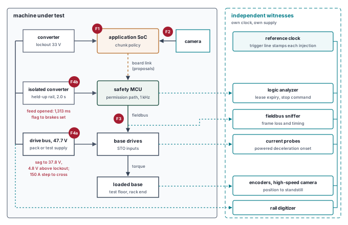
15.8.2 Timing faults across clock domains
Because camera frame capture, trajectory proposal generation, enforcer permission ticks, and fieldbus communication cycles run across asynchronous clock domains (Dating and Placing the Measurement), a fault injected at a fixed offset from the start of a run can miss the narrow alignment where a race condition trips. Reproducible qualification therefore records the disturbance’s phase relative to every relevant clock edge and sweeps across injection phases to expose race conditions that fixed-offset tests miss, while recognizing that empirical phase sweeps alone cannot prove the absence of a worse alignment.
Consider the stale-observation scenario (fault F2) running on production silicon. The navigation camera timestamps each image at the moment of physical exposure, and the perception pipeline budgets a maximum age of 51.6 ms upon trajectory dispatch (The latency waterfall). Because the robot travels at 1.3 m/s, it covers 1.3 mm every millisecond. Unbudgeted perceptual latency drains the stopping distance reserve millisecond by millisecond. The 51.8 ms upper-age bound, however, governs only the dispatch instant; sensory evidence continues to age as the command traverses validation and motor execution. Consequently, the per-tick safety monitor cannot treat the dispatch limit as an open-ended pass; it must evaluate perceptual freshness dynamically against remaining stopping distance and active trajectory validity. The stall that matters is short. Once the dispatch-to-admission allocation is charged, only 37.5 ms of the aisle-speed spare remains (section 15.2), so an undetected stall of that length leaves the machine no clearance to give.
Neither the nominal sensor readout latency from a component datasheet nor the timestamp logged on an isolated image frame proves when the safety enforcer will recognize a stall. Relying on empirical p99 response times provides no safety guarantee because a percentile alone does not bound shared-memory interference; a finite worst-case claim requires an explicit architectural and scheduling model (Response time analysis and execution variance). A defensible containment claim demands an analytic and experimental worst-case detection bound validated across maximum compute saturation, peak fieldbus load, and extreme operating temperatures.
15.8.3 Distributed clock drift and synchronization blackouts
Two processors can each meet every local real-time deadline on their own crystals and still drift apart fast enough during a brief synchronization blackout to let a stale camera frame pass as fresh. The F2 stale-observation detector relies directly on the 0.2 ms clock-conversion bound established in the observation contract of The Observation Contract when translating image capture timestamps into the safety microcontroller’s local timebase. That bound is not an axiomatic constant: Qualifying the claimed error measures it from the tail of the synchronization offset, the path asymmetry, and the drift between synchronization exchanges, and verification asks how much of it survives when those exchanges stop arriving. Consider illustrative oscillator tolerances: ±100 ppm for the application processor crystal, ±50 ppm for the safety microcontroller, and an additional 50 ppm worst-case thermal drift unaccounted for in standard room-temperature ratings. Together, these sources yield a maximum relative drift rate of 200 ppm. At this rate, uncorrected drift alone exhausts the entire 0.2 ms conversion budget in just 1 s without active resynchronization. Under healthy operating conditions, periodic synchronization packets arriving every 100 ms confine accumulated drift to 20 μs, leaving the remainder of the error budget for network transit jitter and software conversion overhead.
Suppose electrical noise or packet collisions trigger a synchronization blackout where three consecutive sync frames are dropped, leaving two successful packets separated by 400 ms. Across this four-period blackout window, bounded clock drift alone accumulates to 80 μs. When measured synchronization jitter has a standard deviation of \(\TimingJitter\) = 15 μs, combining the drift rate \(\ClockSynchronizationSkew\) over the blackout duration \(\SynchronizationBlackout\) with a one-sigma jitter excursion yields: \[\BlackoutClockConversionError=\ClockSynchronizationSkew\,\SynchronizationBlackout+\TimingJitter \tag{2}\] totaling 95 μs. The one-sigma estimate in equation 2 represents an illustrative operating point rather than a deterministic upper bound; certifying real-time safety requires bounding tail jitter analytically and stress-testing the conversion path on hardware. If the blackout extends to a fifth period (four consecutive frames dropped), accumulated oscillator drift alone reaches 100 μs before jitter is added, consuming fully half of the 0.2 ms error budget. The runtime must refuse proposals or enter its qualified fallback before synchronization uncertainty exceeds the conversion bound. If that guard is absent and clock drift or transit jitter breaches the boundary, two failure modes threaten the machine. In the first failure mode, a fresh camera frame appears artificially aged when compared against a fast microcontroller clock; the enforcer rejects valid proposals and initiates an unprompted emergency stop, stranding the vehicle mid-aisle. In the second, more dangerous mode, a stale observation appears artificially fresh against a slow microcontroller clock. The conversion error itself is cheap in distance. At 1.3 mm per millisecond, the whole 0.2 ms bound is worth less than a millimeter of travel. What the error corrupts is the refusal verdict. The nominal navigation frame reaches the 51.8 ms refusal threshold exactly at dispatch, so the observation contract of The Observation Contract left that threshold with zero slack. Once drift exceeds the bound, the age check can no longer certify that an admitted frame lies within budget. A frame held back by an F2 stall then passes as fresh whenever the uncorrected drift exceeds the stall’s extra age, and because drift keeps accumulating for as long as synchronization stays lost, the stall the check can miss grows with the blackout, letting the permission path admit proposals computed from obstacle coordinates older than the budget allows while the loaded base moves at 1.3 m/s.
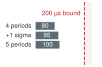
A five-period blackout spends half the clock-conversion bound.
Every physical fault injection trial concludes with a rigorous evidentiary burden. The test harness must simultaneously record the trip signal from the internal detector, the precise timestamp of proposal rejection, the actuation takeover at the motor drives, and the final physical stopping trajectory. All measurements must be captured by external, fault-isolated instruments synchronized to a single master reference clock. If a trial fails to record any of these intermediate transitions, it fails to produce actionable verification evidence. Physical fault injection campaigns do not yield simple pass/fail tallies; they generate auditable execution traces binding each trial to its architectural claim, its exact operating envelope, its software build artifacts, and its physical sensor waveforms.
↪ How these trial traces enter a safety case as evidence for a claim is developed in Safety Cases and Claims.
15.9 Searching Beyond the First Trial
A single successful fault trial demonstrates that the safety path can arrest the vehicle under one declared set of operating conditions. Physical machinery, however, rarely fails under tidy nominal conditions; subtle vulnerabilities hide in the narrow corners of the state space where timing jitter, payload shifts, and degraded surface traction align against the enforcer. Exhaustive testing across this continuous operational envelope is physically impossible, yet uniform random sampling requires an intractable number of runs to uncover rare edge-case failures. Searching beyond isolated trials requires systematically steering disturbances toward the boundary conditions that drive the system closest to its safety limits. Rather than replacing the formal coverage record, automated search routines prioritize which candidate executions deserve empirical evaluation on the physical test track or dynamometer.
15.9.1 Signal temporal logic and quantitative robustness
A binary PASS or FAIL verdict tells an automated search algorithm nothing about whether a passing stop cleared the rack by 15 cm or by 1 mm, leaving the optimizer blind to near misses. Whereas classical temporal logic (Pnueli 1977) checks whether a sequence of states satisfies a property, Signal Temporal Logic (STL) extends the specification to continuous time and real-valued physical signals—such as staying inside a spatial corridor or halting before a deadline (Maler and Nickovic 2004)—and equips every formula with quantitative robustness semantics (Fainekos and Pappas 2009). Instead of returning a boolean flag, quantitative robustness computes a real-valued signed margin \(\StlRobustness(\StlFormula, \SignalTrajectory, \TimeInstant) \in \mathbb{R}\) that measures how far a trajectory \(\SignalTrajectory: \mathbb{R}_{\ge 0} \to \mathbb{R}^{\SignalDimension}\) sits from violating or satisfying the temporal property \(\StlFormula\) at time \(\TimeInstant\).
↪ The syntax and semantics of signal temporal logic are developed in Signal Temporal Logic and Continuous Robustness.
For an atomic physical predicate \(\pi \equiv (\StlPredicateFunction(\SignalTrajectory(\TimeInstant)) \ge 0)\) (such as spatial clearance \(\ObstacleSeparationDistance(\TimeInstant) - \SafeSeparationDistance \ge 0\)), quantitative robustness evaluates the signed predicate margin: \(\StlRobustness(\pi, \SignalTrajectory, \TimeInstant) = \StlPredicateFunction(\SignalTrajectory(\TimeInstant))\). Across temporal operators, safety invariants evaluate worst-case (minimum) margins, whereas reachability deadlines evaluate best-case (maximum) margins: \[\StlRobustness(\square_{[0, \FiniteTimeHorizon]} \StlFormula, \SignalTrajectory, 0) = \min_{t \in [0, \FiniteTimeHorizon]} \StlRobustness(\StlFormula, \SignalTrajectory, \TimeInstant), \qquad \StlRobustness(\lozenge_{[0, \StlEventuallyDeadline]} \StlFormula, \SignalTrajectory, 0) = \max_{t \in [0, \StlEventuallyDeadline]} \StlRobustness(\StlFormula, \SignalTrajectory, \TimeInstant). \tag{3}\] Here \(\square_{[0,\FiniteTimeHorizon]}\) denotes “always on \([0, \FiniteTimeHorizon]\)” and \(\lozenge_{[0,\StlEventuallyDeadline]}\) denotes “eventually within \(\StlEventuallyDeadline\).”
The sign and magnitude of \(\StlRobustness\) in equation 3 establish an immediate operational interpretation: \[\StlRobustness > 0 \implies \text{satisfied with positive margin } \StlRobustness, \qquad \StlRobustness < 0 \implies \text{violated with shortfall depth } |\StlRobustness|.\] For example, if the spatial clearance margin is \(\StlRobustness = +0.15\text{ m}\), the minimum clearance observed along the trajectory exceeded the safety threshold by 15 cm. Conversely, if \(\StlRobustness = -0.04\text{ m}\), the machine breached the prescribed clearance boundary by 4 cm, with physical collision depending on whether the safety limit included an explicit standoff buffer.
This signed value margin constitutes space robustness, quantifying how far the signal’s physical magnitude can perturb before the verdict flips. Space robustness captures amplitude margins rather than timing margins: a delayed brake actuation represents a temporal shortfall rather than an instantaneous spatial error. Capturing temporal slack requires time robustness, a complementary semantics that evaluates how far a signal trajectory may shift along the time axis before the verdict changes (Donzé and Maler 2010). Because spatial and temporal margins govern fundamentally different physical dimensions, combining them into a single unweighted formula introduces semantic ambiguity. For the F1 specification, the cleanest engineering formulation isolates the onset deadline outside the Signal Temporal Logic expression as an explicit scalar predicate on measured reaction time, while evaluating stopping distance via spatial robustness.
Donzé, Alexandre, and Oded Maler. 2010. “Robust Satisfaction of Temporal Logic over Real-Valued Signals.” Formal Modeling and Analysis of Timed Systems (FORMATS), Lecture notes in computer science, vol. 6246: 92–106. https://doi.org/10.1007/978-3-642-15297-9_9.
For this reason equation 1 keeps its two predicates apart. The onset predicate, deceleration within 82 ms of the last valid renewal, is a scalar check on measured reaction time, and the travel predicate, at most 751.9 mm at aisle speed, is a space-robustness predicate on vehicle position. Both are measured from the same reference event, so neither can silently absorb slack from the other; a different reference event would change the elapsed timing and require a correspondingly adjusted distance bound.
To illustrate this dual evaluation numerically, consider an F1 trace at aisle speed, timed channel by channel in figure 4, where powered deceleration begins 30 ms late, occurring 112 ms after the last valid renewal. The onset margin against the 82 ms bound evaluates to -30 ms. Because the mobile base travels 39 mm further before braking engages, total travel from renewal to rest reaches 750.9 mm, yielding a distance margin of 1 mm against the 751.9 mm oracle. The onset predicate fails, while nominal travel remains within the distance allowance. The verification results retain both margins in their native physical units; the tracking inset belongs in the oracle and is not additional travel in the plotted speed integral. Because taking an unweighted minimum across milliseconds and millimeters produces an uninterpretable quantity, synthesizing them into a unified score via min requires normalizing each margin by a predeclared positive scale in its corresponding unit. Logging both the raw margins and their normalization factors ensures the synthesized verdict remains physically meaningful. Choosing scales equal to the verification bounds themselves yields normalized margins of -0.366 for onset timing and 0.001 for stopping distance, making the onset predicate the governing term in the combined score. When several predicates have negative margins, alternative scales can change which one governs the compound score, so test engineers must fix normalization factors before executing verification runs. In this nominal trace only onset fails, so positive rescaling cannot make distance the governing predicate. These numerical values reflect model arithmetic over a stipulated reference trace rather than empirical physical measurements.
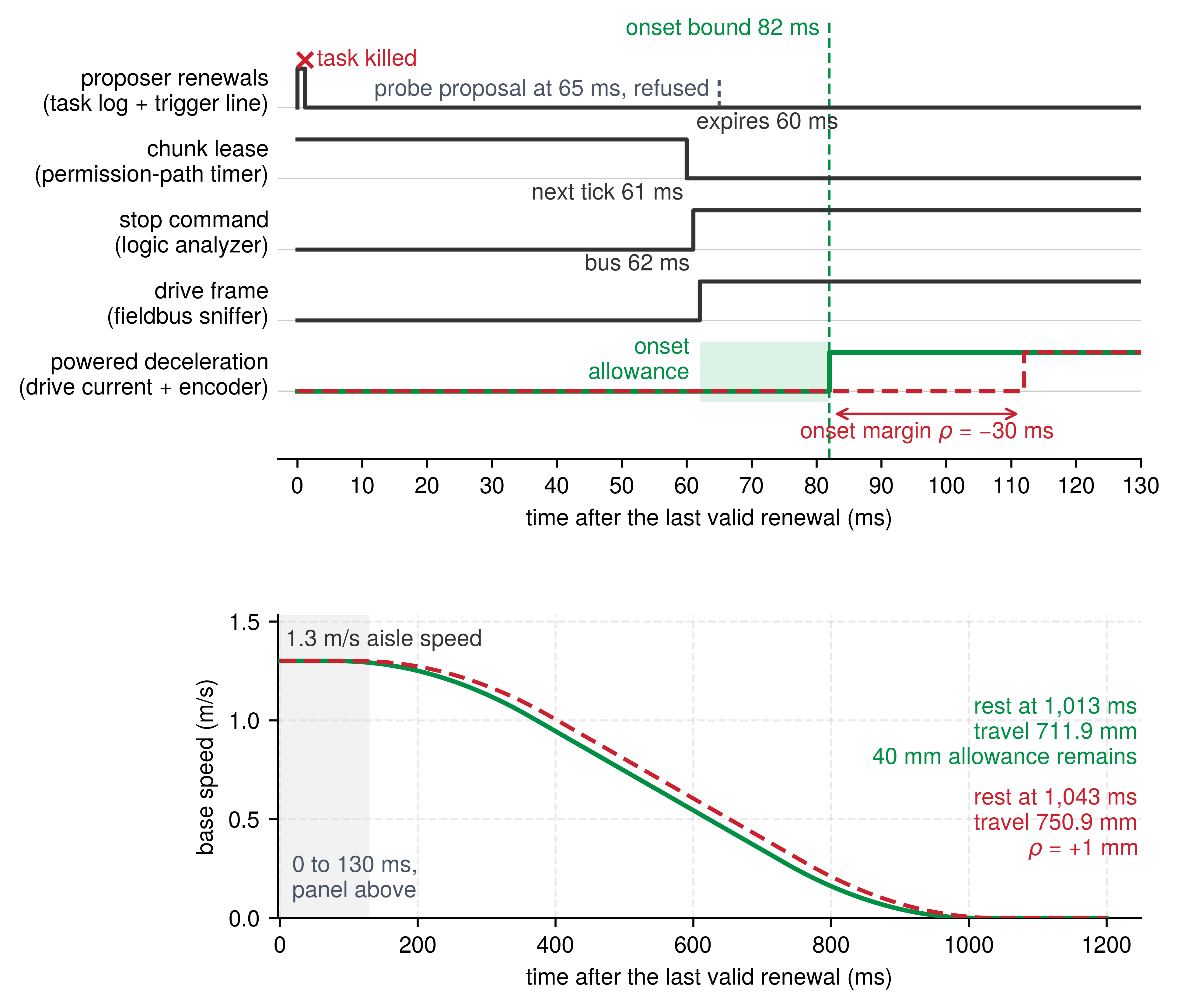
Recording every monitored channel on one timeline, as illustrated in figure 4, helps localize a failed trial to a stage of the response path when the independent witnesses remain valid. A lease that expires on schedule and a stop command issued at the very next tick, followed by a late braking onset, direct the investigation toward command delivery, drive execution, or physical brake response rather than the lease-expiry check.
By producing a continuous, signed margin rather than a binary pass/fail flag, quantitative robustness transforms verification from passive testing into temporal logic falsification as adversarial optimization. In classical computer vision and deep learning, adversarial attacks such as the fast gradient sign method (FGSM) (Goodfellow et al. 2015) and projected gradient descent (PGD) (Madry et al. 2018) search for an input perturbation \(\AdversarialPerturbation\) bounded within an \(\AdversarialPerturbationBudget\)-ball (\(\|\AdversarialPerturbation\|_\infty \le \AdversarialPerturbationBudget\)) that maximizes task loss: \(\max_{\|\AdversarialPerturbation\|_\infty \le \AdversarialPerturbationBudget} \LossFunction(\ParameterizedPredictor(\ModelInput + \AdversarialPerturbation), \ExampleLabel)\). In cyber-physical systems, temporal logic falsification provides the continuous dynamic counterpart. Rather than perturbing static feature vectors, an adversarial optimizer searches over initial state spaces and time-varying physical disturbance trajectories within a bounded physical disturbance envelope to minimize quantitative Signal Temporal Logic robustness. The robustness metric \(\StlRobustness\) acts directly as the adversarial objective function. Whereas uniform random sampling across a high-dimensional operational state space requires an intractable number of physical trials to expose rare corner-case collisions, an adversarial falsification engine actively steers disturbance sequences toward trajectories that drive the system closest to violating its safety invariants.
Goodfellow, I. J., J. Shlens, and C. Szegedy. 2015. “Explaining and Harnessing Adversarial Examples.” International Conference on Learning Representations (ICLR).
Madry, Aleksander, Aleksandar Makelov, Ludwig Schmidt, Dimitris Tsipras, and Adrian Vladu. 2018. “Towards Deep Learning Models Resistant to Adversarial Attacks.” International Conference on Learning Representations (ICLR).
15.9.2 Formulating falsification as trajectory optimization
An unconstrained mathematical search over arbitrary disturbance signals can easily invent discontinuous spikes that no real actuator, sensor, or contact surface can physically produce, wasting the search on impossible counterexamples. To restrict the search to physically realizable disturbances, let \(\MechanicalPlantState_0 \in \FalsificationInitialStateSet\) represent the machine’s initial state vector (translational speed, payload mass, heading angle, and battery state-of-charge), and let \(\DisturbanceTrajectory(\TimeInstant) \in \AdmissibleDisturbanceSet\) denote an adversarial disturbance trajectory spanning the test horizon \([0, \FiniteTimeHorizon]\). Because physical hardware has finite bandwidth, mechanical inertia, and thermal limits, disturbance trajectories are parameterized over a compact parameter space \(\DisturbanceParameterVector \in \DisturbanceParameterSet\) using smooth basis functions, such as B-splines, cubic splines, or Fourier series: \[\DisturbanceTrajectory(\TimeInstant; \DisturbanceParameterVector) = \sum_{k=1}^{\DisturbanceBasisCount} \DisturbanceBasisCoefficient_k \DisturbanceBasisFunction_k(\TimeInstant)\] where \(\DisturbanceBasisFunction_k(\TimeInstant)\) are time-dependent basis functions and \(\DisturbanceBasisCoefficient_k\) are bounded parameter coefficients.
The temporal logic falsification problem finds the worst-case parameter combination that minimizes quantitative robustness: \[\min_{\MechanicalPlantState_0 \in \FalsificationInitialStateSet, \, \DisturbanceParameterVector \in \DisturbanceParameterSet} \StlRobustness(\StlFormula, \SignalTrajectory(\MechanicalPlantState_0, \DisturbanceTrajectory(\DisturbanceParameterVector)), 0) \quad \text{subject to} \quad \|\DisturbanceTrajectory(\TimeInstant; \DisturbanceParameterVector)\|_\infty \le \DisturbanceBudget, \quad \forall \TimeInstant \in [0, \FiniteTimeHorizon]. \tag{4}\]
The disturbance budget \(\DisturbanceBudget\) in equation 4 bounds the peak magnitude of optical, acoustic, contact, and execution disturbances derived from the operational envelope. Yet magnitude bounds alone do not guarantee that a test bench can deliver the waveform. The basis functions, coefficient bounds, and experimental test fixtures must also respect realistic rates of change and duration limits. For example, a programmable load bank that cannot slew fast enough to replicate a steep simulated voltage transient leaves that synthesized counterexample untested on hardware.
A verification campaign must therefore log both the synthesized disturbance command and its independently measured physical trace. If the test fixture fails to deliver the precommitted disturbance trajectory within specified tolerances, the trial is INVALID for that test condition even if the machine comes to a safe stop. Conversely, while an empirically realized counterexample refutes a safety claim outright, a search that finds no violation within a restricted parameter family leaves arbitrary disturbances outside that basis open to question.
15.9.3 Selecting a search method
Frictional contact transitions and discrete controller state jumps often make the quantitative robustness landscape nonsmooth and non-convex, causing gradient descent to stall or step in the wrong direction unless those transitions are smoothed or handled explicitly. Derivative-free optimizers avoid this trap. The Covariance Matrix Adaptation Evolution Strategy (CMA-ES) (Hansen and Ostermeier 2001) updates a multivariate normal distribution over disturbance parameters across generations, discovering correlated failure modes across speed, surface friction, and execution timing. When physical trials dominate the cost because each run requires mechanical resets, hardware inspection, and thermal cool-down, Bayesian optimization10 fits a probabilistic surrogate model to previous runs to choose the next test point. Neither method guarantees convergence to a global minimum over a finite campaign, so the verification record must preserve search parameter bounds, random seeds, evaluated test vectors, and fixture limits so that auditors can see exactly which regions were challenged.
Hansen, Nikolaus, and Andreas Ostermeier. 2001. “Completely Derandomized Self-Adaptation in Evolution Strategies.” Evolutionary Computation 9 (2): 159–95. https://doi.org/10.1162/106365601750190398.
10 Bayesian Optimization: Originally developed for computationally expensive engineering simulations, Bayesian optimization fits a Gaussian-process surrogate across completed trials and selects the next sample point by maximizing expected improvement (Jones et al. 1998). Physical fault-injection rigs face the same cost structure, because each trial requires mechanical resets, hardware inspection, and thermal stabilization delays. Still, the surrogate’s confidence is only a model prediction: a region it estimates to be safe has not been physically tested simply because the surrogate predicts a positive margin.
Jones, Donald R., Matthias Schonlau, and William J. Welch. 1998. “Efficient Global Optimization of Expensive Black-Box Functions.” Journal of Global Optimization 13 (4): 455–92. https://doi.org/10.1023/A:1008306431147.
Lee, Ritchie, Ole J. Mengshoel, Anshu Saksena, Ryan W. Gardner, Daniel Genin, Joshua Silbermann, Michael Owen, and Mykel J. Kochenderfer. 2020. “Adaptive Stress Testing: Finding Likely Failure Events with Reinforcement Learning.” Journal of Artificial Intelligence Research 69: 1165–201. https://doi.org/10.1613/jair.1.12190.
Two software toolboxes implement this search loop for cyber-physical models: S-TaLiRo (Annpureddy et al. 2011) and Breach (Donzé 2010). Both ingest a formal Signal Temporal Logic requirement and a simulation model, compute quantitative robustness on each simulated rollout, and steer stochastic or local optimizers toward negative robustness. A related family of algorithms treats the disturbance sequence as a sequential decision process. Adaptive stress testing (Lee et al. 2020) explores the disturbance sequence via Monte Carlo tree search or reinforcement learning to find the most probable path to failure rather than an arbitrary, physically improbable edge case, ranking counterexamples by operational plausibility. A survey of these black-box methods groups them by their output (Corso et al. 2021): finding an isolated counterexample, finding the most likely failure trajectory, or estimating an aggregate failure probability. Only the third output measures operational risk, using the estimation procedure developed in section 15.10.2. Whatever search method is chosen, it returns candidate counterexamples and measured robustness margins; when those margins come from a simulator, counting them toward a physical safety claim requires bounding how far the simulator’s trajectories can drift from the real machine’s.
15.9.4 Bounding the sim-to-real transfer gap
A simulator that passes every fault-injection rollout can still hide a physical crash if its modeled trajectories differ from the real machine’s by more than the simulated safety margin. While high-throughput software-in-the-loop simulation is indispensable for exploring combinatorial corner cases, an unvalidated simulator can confirm only what its underlying model assumes. To use simulation sweeps as evidence in a safety case, the engineering team must validate and bound the sim-to-real transfer gap \(\TransferDiscrepancyBound\).
Let \(\SimulatedStateTrajectory(\TimeInstant; \SimulationParameterVector, \ControlInput) \in \TrajectoryStateSpace\) and \(\PhysicalStateTrajectory(\TimeInstant; \SimulationParameterVector, \ControlInput) \in \TrajectoryStateSpace\) denote the system state trajectories in simulation and on target physical hardware under matched declared conditions \(\SimulationParameterVector\) (initial speed, payload mass, floor friction) and control input history \(\ControlInput\). Replaying identical open-loop input sequences establishes a baseline comparison of plant dynamics, but certifying a deployed closed-loop policy requires bounding discrepancy under autonomous execution, where perturbed sensor observations produce divergent actuator commands. The continuous transfer discrepancy is the supremum state error across the test horizon \([0, \FiniteTimeHorizon]\) under a task-weighted physical norm: \[\TransferDiscrepancyBound = \sup_{t \in [0, \FiniteTimeHorizon]} \|\PhysicalStateTrajectory(\TimeInstant) - \SimulatedStateTrajectory(\TimeInstant)\|_{\StateNormWeighting} \tag{5}\] where \(\|\cdot\|_{\StateNormWeighting}\) normalizes position, velocity, and actuator torque errors by predeclared positive reference scales in meters, meters per second, and newton-meters, respectively, before applying dimensionless task weights. The verification plan fixes those scales and weights in advance; the resulting discrepancy \(\TransferDiscrepancyBound\) is dimensionless, while the Lipschitz constant \(\PredicateLipschitzConstant\) carries the physical units of the predicate margin.
A sound safety warrant requires a discrepancy bound that holds across all trajectories in the claimed operational envelope, not just the largest error observed in a small test sample. That modeling error must be deducted directly from the simulated robustness margin. Consider a Signal Temporal Logic safety requirement \(\StlFormula\) whose atomic predicates \(\StlPredicateFunction(\SignalTrajectory(\TimeInstant)) \ge 0\) are Lipschitz continuous with constant \(\PredicateLipschitzConstant = \sup_{\SignalTrajectory_1 \ne \SignalTrajectory_2} |\StlPredicateFunction(\SignalTrajectory_1) - \StlPredicateFunction(\SignalTrajectory_2)| / \|\SignalTrajectory_1 - \SignalTrajectory_2\|_{\StateNormWeighting}\). Here \(\PredicateLipschitzConstant\) is the maximum rate at which the predicate margin degrades per unit of normalized state discrepancy; for a spatial clearance predicate evaluated in meters against position error normalized by a 1 m reference scale with unit task weight, \(\PredicateLipschitzConstant\) is 1 m per unit of normalized discrepancy. By Lipschitz continuity, the physical predicate error is bounded pointwise by the state discrepancy: \[|\StlPredicateFunction(\PhysicalStateTrajectory(\TimeInstant)) - \StlPredicateFunction(\SimulatedStateTrajectory(\TimeInstant))| \le \PredicateLipschitzConstant \|\PhysicalStateTrajectory(\TimeInstant) - \SimulatedStateTrajectory(\TimeInstant)\|_{\StateNormWeighting} \le \PredicateLipschitzConstant \TransferDiscrepancyBound\] which guarantees that at every instant \(\TimeInstant \in [0, \FiniteTimeHorizon]\): \[\StlPredicateFunction(\PhysicalStateTrajectory(\TimeInstant)) \ge \StlPredicateFunction(\SimulatedStateTrajectory(\TimeInstant)) - \PredicateLipschitzConstant \TransferDiscrepancyBound.\] Taking the infimum across the temporal horizon \(\TimeInstant \in [0, \FiniteTimeHorizon]\) for an invariance property \(\StlFormula \equiv \square_{[0, \FiniteTimeHorizon]} (\StlPredicateFunction(\SignalTrajectory(\TimeInstant)) \ge 0)\), the guaranteed lower bound on physical robustness in the real world is: \[\PhysicalStlRobustness \ge \SimulatedStlRobustness - \PredicateLipschitzConstant \TransferDiscrepancyBound. \tag{6}\] The term \(\PredicateLipschitzConstant \TransferDiscrepancyBound\) in equation 6 acts as a sim-to-real robustness discount. If simulated robustness \(\SimulatedStlRobustness\) does not exceed \(\PredicateLipschitzConstant \TransferDiscrepancyBound\), the simulation pass guarantees no physical margin at all: the real machine can breach the safe invariant set (\(\PhysicalStlRobustness < 0\)) even when every simulated rollout returns a positive margin.
The rack-end claim makes this discount concrete. Scoring the distance predicate in meters and normalizing position error by a 1 m reference scale with unit task weight gives a Lipschitz constant of 1 m per unit of normalized discrepancy. Suppose a simulated stop finishes with the entire 131.0 mm reserve intact. The lower bound in equation 6 certifies a positive physical margin when \(\TransferDiscrepancyBound <\) 0.131, meaning the justified position-error bound is smaller than the reserve under this normalization. A larger discrepancy bound leaves the actual physical margin unresolved. A simulator whose stopping position is experimentally validated to within a few centimeters transfers nearly all of its verified margin; a simulator that has never been calibrated against physical stopping runs transfers none of it.
Coupled cyber-physical dynamics determine what this discount must cover: drivetrain compliance and gear backlash alter delivered torque, surface contamination and tire wear change braking traction, and real-time execution jitter shifts braking onset time. A discrepancy bound calibrated on an unloaded, cool machine cannot be silently extended to a loaded vehicle operating under thermal throttling. The verification record must state the operational envelope across which the discrepancy bound holds, keeping that justified bound distinct from the empirical maximum error observed during paired test runs.
Measuring the empirical discrepancy \(\EmpiricalTransferDiscrepancy\) builds on the paired probing protocols used to qualify simulation models for policy training, driving identical command histories into both simulated and physical hardware while scoring channel residuals against precommitted tolerances (The sim-to-real contact exploit), the same measurements that bound a simulator’s screening validity in Simulation as a conditional proxy. Verification adapts this qualification procedure in two ways. First, excitation inputs are tailored to the specific safety invariant under test, such as full-rate deceleration from aisle speed for the rack-end claim rather than low-speed docking maneuvers. Second, physical trajectories must be captured with external instrumentation independent of the robot’s onboard sensor suite, so that shared sensor calibration errors or estimator drift cannot cancel out of the residual. The resulting empirical discrepancy \(\EmpiricalTransferDiscrepancy\) is archived in the test records alongside the environmental conditions under which it was gathered. If the sim-to-real safety case relies on domain randomization distributions \(\DomainRandomizationDistribution\) to cover hardware variations, it must justify set inclusion across all declared operational conditions: \[\PhysicalTrajectorySet(\SimulationParameterVector) \subseteq \bigcup_{\SampledSimulationParameterVector \sim \DomainRandomizationDistribution} \SimulatedTrajectorySet(\SampledSimulationParameterVector).\] Finite paired measurements can falsify this inclusion by exposing an outlier, but they cannot prove it globally. If unmodeled physical effects such as fieldbus latency jitter, magnetic stator saturation, transmission backlash, or Coulomb stiction cause physical trajectories to escape the randomized simulation bundle, the sim-to-real transfer guarantee fails, and software-in-the-loop simulation passes cannot serve as evidence in the release safety case.
Checkpoint 15.3: Search, robustness, and transfer
A signed margin turns testing into search, and a simulated margin counts toward a physical claim only after its transfer discount.
15.10 Interpreting Campaign Statistics
Counting passed trials in an adversarial campaign can easily mislead a release review into treating a test-bench success rate as an operational reliability number. Any statistical summary describes only the specific population sampled by the test harness, and conditions that were never tested remain missing evidence no matter how sophisticated the statistical model applied afterward.
When \(\ZeroFailureTrialCount\) independent Bernoulli trials sampled from a declared fault distribution yield zero missed mitigations, the outcome puts a one-sided upper confidence limit on the miss probability for that specific distribution. This is the zero-failure trial sizing of Sample size requirements per empirical claim, applied here to an injected hardware fault population rather than closed-loop policy rollouts; at a 95 percent confidence level, it requires about \(3/\TrialFailureProbability\) consecutive successful injections to bound the miss probability below \(\TrialFailureProbability\). To turn these injection counts into a hardware coverage claim weighted by each component’s failure rate in FIT (failures in time, one per \(10^9\) operating hours; notebook 15.3 gives the component weights \(\ComponentFailureRate_i\)), the injection harness must sample faults in direct proportion to their raw failure rates \(\ComponentFailureRate_i\), or the verification pipeline must apply an explicitly justified stratified weighting across each fault stratum.11
11 Trial sampling and aging: The binomial count assumes independent, identically distributed Bernoulli outcomes under the declared injection distribution; it does not require Poisson event arrivals. Repeated heating, mechanical wear, or contact changes can break independence and require a state-stratified experimental design.
This statistical bound holds only when the physical trials satisfy the declared independence and sampling assumptions. On real hardware, repeated high-energy stops produce Joule heating (\(\WindingCurrent^2\ElectricalResistance\)) in the drive motor windings and mechanical brake linings. That heat buildup changes winding resistance and lining friction coefficients, coupling successive trials. As a result, a test campaign run on a dry aisle at room temperature cannot support a confidence bound for a contaminated floor or for the operating envelope’s 5 °C thermal extreme.
Notebook 15.3 draws its rates from four component strata (sensors, compute, transceivers and power management, gate drivers), and each stratum maps onto rows of table 2. Sensor faults are injected as F2 and as the physical transducer disturbances, compute faults as F1, transceiver and power-management faults as F3 and F4, and gate-driver faults as the drive that keeps producing torque after a stop command (section 15.6.2). Sampling in proportion to those rates therefore fixes how the campaign’s trials divide among the rows.
Napkin Math 15.3: The coverage count
Problem: Illustrative component fault rates and a chosen ceiling on the unmitigated rate fix the diagnostic coverage the machine needs. How many zero-miss injections, sampled in proportion to those rates, would demonstrate that coverage?
Variables:
- Component fault rates \(\ComponentFailureRate_i\) in FIT, one fault per \(10^9\) operating hours (Illustrative): sensors 1,500, compute 1,000, transceivers and power management 2,500, and gate drivers 4,800.
- Target unmitigated rate \(\TargetHazardRate =\) 100 FIT, with a stricter 10 FIT alternative, at confidence \(\ConfidenceLevel =\) 95 percent (Chosen).
- Diagnostic coverage \(\DiagnosticCoverage\), the \(\ComponentFailureRate_i\)-weighted fraction of faults whose hazardous effect is mitigated, so that \(\UnmitigatedHardwareFaultRate = \RawHardwareFaultRate(1 - \DiagnosticCoverage)\) and a single injection misses with probability \(\TrialFailureProbability = 1 - \DiagnosticCoverage\).
Math:
Required coverage. \[\lambda_{\text{raw}} = 1500 + 1000 + 2500 + 4800 = 9800\ \text{FIT}, \qquad C_{\text{diag}} \ge 1 - \frac{\lambda_{\text{target}}}{\lambda_{\text{raw}}} = 1 - \frac{100}{9800} = 0.9898\]
Injections to demonstrate it, from the zero-failure count of Sample size requirements per empirical claim. \[n \ge \frac{\ln(1 - C)}{\ln C_{\text{diag}}} = \frac{\ln 0.05}{\ln 0.9898} = 292.1 \;\Rightarrow\; n = 293, \qquad \frac{3}{p} = \frac{3 \lambda_{\text{raw}}}{\lambda_{\text{target}}} = \frac{3 \times 9800}{100} = 294\]
Sensitivity. The count scales as \(3\RawHardwareFaultRate/\TargetHazardRate\), so the 10 FIT target needs 99.90 percent coverage and 2,935 injections, against a rule-of-three estimate of 2,940.
Result: A 100 FIT target needs 98.98 percent coverage, which 293 zero-miss injections demonstrate at 95 percent confidence.
Systems insight: The target unmitigated failure rate, not the number of entries in the fault list, governs campaign size. Every tenfold tightening of the target rate demands roughly a tenfold increase in physical injection runs. Furthermore, this sample size holds only when injections are drawn in proportion to each component’s raw failure rate \(\ComponentFailureRate_i\). Injecting uniformly across components with disparate failure rates tests a distorted distribution unless the harness weights the empirical outcomes and gathers enough trials within every stratum. Every trial must therefore log the exact injected mode, whether hardware detection triggered within the deadline, and whether the safety controller brought the plant to a verified safe state.
Even within the declared fault strata, a campaign rarely reaches every combination of load, floor friction, and temperature. The fault-record set must therefore catalog omitted test cases as carefully as completed runs, recording every parameter region skipped because of testbed physical limits, sensor bandwidth limits, or destructive testing costs. Unprobed regions cannot count as verified safety margins in the release case, nor can passive operational hours accumulated outside the test cell fill those gaps.
15.10.1 Exposure and the population a statistic describes
Logging thousands of incident-free fleet hours in normal warehouse aisles cannot bound rare safety-critical faults or substitute for targeted fault injection, because passive operation samples a different distribution from deliberate fault trials. Fleet exposure runs into the exposure wall of equation 7.9: bounding a hazard rate \(\TargetHazardRate\) at 95 percent confidence requires about \(3/\TargetHazardRate\) failure-free operating hours, which Butler and Finelli (1993) showed is unreachable at safety-critical rates such as \(10^{-9}\) failures per hour. Pooling those hours across a fleet adds exposure time but not environmental diversity, so the bound covers only the conditions the pooled machines share (Verification Ceilings and the Exposure Wall), and normal fleet traffic rarely triggers the corner-case hardware faults this chapter injects. Verification also has to ask which configuration those hours describe. Any change to a safety filter, control policy, or actuator driver can alter the sampled outcomes, so earlier fleet hours count toward the updated configuration only when an explicit engineering argument shows that the change left the counted events unaffected. When a rare failure rate must be estimated across a high-dimensional disturbance space without waiting for billions of passive rollouts, the campaign must steer samples toward the failure region and weight them back to the operational distribution.
Butler, Ricky W., and George B. Finelli. 1993. “The Infeasibility of Quantifying the Reliability of Life-Critical Real-Time Software.” IEEE Transactions on Software Engineering 19 (1): 3–12. https://doi.org/10.1109/32.210303.
15.10.2 Estimating a rare failure rate by importance sampling
Naive Monte Carlo sampling from nominal operating conditions cannot estimate rare safety-critical failure rates because nearly every rollout ends in an unremarkable, safe stop, requiring billions of runs to observe even a handful of violations (section 15.10.1). While adversarial falsification finds whether an unsafe trajectory exists, release decisions also need to know how often such failures occur under nominal operating conditions. Importance sampling12 breaks this bottleneck by drawing rollouts from an alternative proposal distribution that concentrates samples near the failure boundary and then weighting each sample by its likelihood ratio to recover an unbiased estimate under the operational distribution.
12 Importance Sampling: The technique originated in Monte Carlo calculations of nuclear radiation shielding in the early 1950s, where the few particles that penetrated dense shielding were exceptionally rare yet critical to safety. Kahn and Marshall (1953) formalized importance sampling alongside correlated sampling and statistical estimation to cut required sample counts. The method carries a sharp failure mode of its own: a proposal distribution that omits a valid failure path reports tiny sample variance and an erroneously low failure probability, a support failure that diagnostic checks must catch.
Kahn, Herman, and Andrew W. Marshall. 1953. “Methods of Reducing Sample Size in Monte Carlo Computations.” Journal of the Operations Research Society of America 1 (5): 263–78. https://doi.org/10.1287/opre.1.5.263.
Let the operational distribution of uncertain input parameters \(\UncertainScenarioParameters\) be denoted by \(\OperationalScenarioDistribution(\UncertainScenarioParameters)\), and let \(\FailureRegion\) define the subset of conditions leading to a safety violation. Standard Monte Carlo estimation evaluates the failure probability \(\OperationalFailureProbability = \Pr_{\OperationalScenarioDistribution}(\UncertainScenarioParameters \in \FailureRegion)\) by computing the empirical failure fraction across \(\EstimatorDrawCount\) independent draws from \(\OperationalScenarioDistribution\). Importance sampling instead draws samples from an engineered proposal distribution \(\ImportanceProposalDistribution(\UncertainScenarioParameters)\) and weights each outcome by the likelihood ratio \(\LikelihoodRatioWeight(\UncertainScenarioParameters) = \OperationalScenarioDistribution(\UncertainScenarioParameters)/\ImportanceProposalDistribution(\UncertainScenarioParameters)\): \[\ImportanceSampledFailureProbability = \frac{1}{\EstimatorDrawCount}\sum_{i=1}^{\EstimatorDrawCount} \mathbb{1}[\UncertainScenarioParameters_i \in \FailureRegion]\, \LikelihoodRatioWeight(\UncertainScenarioParameters_i), \qquad \UncertainScenarioParameters_i \sim \ImportanceProposalDistribution. \tag{7}\] This estimator remains mathematically unbiased as long as \(\ImportanceProposalDistribution(\UncertainScenarioParameters) > 0\) whenever \(\OperationalScenarioDistribution(\UncertainScenarioParameters)\mathbb{1}[\UncertainScenarioParameters \in \FailureRegion] > 0\), since the likelihood weight corrects for the shift in sampling probability (Owen 2013). The variance of \(\ImportanceSampledFailureProbability\) depends entirely on the geometry of \(\ImportanceProposalDistribution\). The theoretically optimal zero-variance proposal is the operational distribution \(\OperationalScenarioDistribution\) conditioned on the failure region \(\FailureRegion\) (\(\ImportanceProposalDistribution^*(\UncertainScenarioParameters) = \OperationalScenarioDistribution(\UncertainScenarioParameters)\mathbb{1}[\UncertainScenarioParameters \in \FailureRegion] / \OperationalFailureProbability\)). Constructing \(\ImportanceProposalDistribution^*\) directly is impossible because its normalizing constant is the very quantity \(\OperationalFailureProbability\) under estimation. Practical verification pipelines must therefore construct parametric approximations to \(\ImportanceProposalDistribution^*\).
The cross-entropy method (Rubinstein and Kroese 2004) systematically discovers such an approximation within a parameterized distribution family \(\ParametricProposalDistribution\) by solving a sequence of intermediate rare-event problems. Beginning with an initial proposal aligned with the operational profile (\(\InitialProposalDistribution = \OperationalScenarioDistribution\)), the algorithm iteratively draws a sample batch from the current proposal, evaluates the performance metric, and selects an intermediate threshold at the \((1-\EliteSampleFraction)\) quantile so that a fraction \(\EliteSampleFraction\) of the batch qualifies as elite runs. The parameter vector \(\ProposalParameterVector\) is then updated by maximizing the likelihood-weighted log-density of these elite samples, which minimizes the Kullback-Leibler divergence (a measure of how far one probability distribution lies from another) to the optimal proposal on that intermediate slice. As the threshold steps forward across iterations, the proposal gradually shifts its probability mass toward the true failure boundary. For an exponential proposal parameterized by its mean, or a fixed-variance Gaussian proposal parameterized by its mean, this update admits an exact closed form: the updated mean is the weighted empirical mean of the elite draws.
Consider this method applied to the rack-end deceleration scenario. Traveling at nominal aisle velocity, the mobile base consumes its 131.0 mm stopping reserve from section 15.2 in \(\FallbackDeadline =\) 100.8 ms, the latest-fallback deadline of equation 14.4 at aisle speed. Any unbudgeted message queue delay exceeding \(\FallbackDeadline\) exhausts this safety buffer, causing the physical vehicle to breach the clearance boundary. To establish an analytical baseline, assume an illustrative operational distribution where queue delays \(\MessageQueueDelay\) follow an exponential distribution with mean \(\MeanMessageQueueDelay =\) 5 ms (in production verification, latency measurements gathered under the declared load must justify or replace this model). Under this formulation, the analytical failure probability is \(\OperationalFailureProbability = e^{-\FallbackDeadline/\MeanMessageQueueDelay} =\) 1.8 × 10⁻⁹ per stopping event. This closed-form quantity serves as an exact ground truth against which to benchmark competing sampling estimators. The threshold is deliberately the uncharged ceiling of section 15.2, which makes the example optimistic. Charging the dispatch-to-admission allocation leaves only 37.5 ms, and the same delay model then gives \(\OperationalFailureProbability =\) 5.6 × 10⁻⁴, about 3 × 10⁵ times larger. The comparison below keeps the uncharged threshold because there the failure is rarest and the gap between estimators widest; at the charged threshold even plain Monte Carlo would need far fewer runs.
The sample sizing required across these estimators stems directly from the variance of sample averages. When an estimator averages \(\EstimatorDrawCount\) independent draws with mean \(\OperationalFailureProbability\) and per-sample variance \(\EstimatorDrawStandardDeviation^2\), the estimator’s standard deviation is \(\EstimatorDrawStandardDeviation/\sqrt{\EstimatorDrawCount}\), yielding a relative standard error \(\RelativeStandardError = \sqrt{\EstimatorDrawStandardDeviation^2 / (\OperationalFailureProbability^2 \EstimatorDrawCount)}\). Achieving a target relative precision \(\RelativeStandardError\) requires \(\EstimatorDrawCount = (\EstimatorDrawStandardDeviation^2 / \OperationalFailureProbability^2) / \RelativeStandardError^2\) trials, where \(\EstimatorDrawStandardDeviation^2 / \OperationalFailureProbability^2\) denotes the per-draw relative variance. For naive Monte Carlo, each trial is an indicator variable with variance \(\OperationalFailureProbability(1 - \OperationalFailureProbability)\), demanding approximately \((1 - \OperationalFailureProbability)/(\OperationalFailureProbability \RelativeStandardError^2)\) simulated runs. Under the illustrative delay model, securing an estimate with \(\RelativeStandardError =\) 10 percent relative error requires 5.7 × 10¹⁰ trials. By comparison, a zero-failure qualification campaign requires 1.7 × 10⁹ consecutive incident-free runs simply to establish an upper bound at the \(\OperationalFailureProbability\) threshold (equation 7.4). Under importance sampling for this exponential model, the per-draw variance equals the weighted failure indicator’s second moment minus \(\OperationalFailureProbability^2\), which stays finite as long as the proposal rate is less than twice the operational rate.
The cross-entropy method using exponential proposals with an elite fraction of \(\EliteSampleFraction =\) 10 percent demonstrates how adaptive sampling overcomes this barrier. The initial threshold is set at the 90th percentile of the operational delay distribution (\(\MeanMessageQueueDelay\ln 10\), or 11.5 ms). Because the exponential distribution is memoryless, the conditional distribution of delays exceeding any threshold \(\CrossEntropyLevelThreshold\) is identical to the original distribution shifted by \(\CrossEntropyLevelThreshold\). The likelihood-weighted mean of the elite samples is therefore simply \(\CrossEntropyLevelThreshold + \MeanMessageQueueDelay\), which immediately defines the mean for the next proposal. Successive iterations lift the intermediate threshold to 38.0 ms and 99.1 ms. By iteration 4, the intermediate quantile surpasses the critical threshold, clamping the final level at \(\FallbackDeadline\) with a proposal mean of 105.8 ms, the conditional expectation of the delay given a boundary violation. Under this adapted proposal, 38.6 percent of the generated rollouts land in the failure set, and their small likelihood weights scale each observed failure back to the operational probability. The resulting per-draw relative variance drops to 27.1. Consequently, only 2,709 simulation runs are needed to reach the target 10 percent relative error, a factor of 2 × 10⁷ fewer runs than plain Monte Carlo and within 0.1 percent of the best exponential proposal. These numerical counts derive from the assumed exponential model; testing against an empirical delay histogram will yield distinct run requirements.
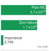
Weighting runs near failure cuts the runs by about 2 × 10⁷ times.
Two statistical diagnostics safeguard the integrity of importance sampling estimates. The first is the effective sample size, defined as \(\EffectiveSampleSize = \left(\sum_{i=1}^{\EstimatorDrawCount} \LikelihoodRatioWeight_i\right)^2 / \sum_{i=1}^{\EstimatorDrawCount} \LikelihoodRatioWeight_i^2\) (Owen 2013). This metric diagnoses concentration of the likelihood weights; it does not by itself establish the precision of the weighted failure estimate, which depends on the variance of the weighted failure indicator. For the 2,709 runs above, the expected effective sample size is approximately 250; a degenerate value approaching 1 would warn that a few outlying weights dominate the summation, rendering the estimate unstable. The second diagnostic is distribution support and tail coverage. Omitting a subregion of \(\FailureRegion\) with positive operational probability violates the support condition and biases the estimate. A proposal that retains support but samples the operational tail too rarely can instead produce unstable or infinite variance, with deceptively small observed variance in a finite run. Sample variance cannot reveal an omitted failure path that generates no samples, so the campaign must justify coverage independently of its weight diagnostics. O’Kelly et al. (2018) applied adaptive importance sampling to end-to-end verification of autonomous driving software stacks and obtained speedups of several orders of magnitude over naive Monte Carlo in estimating rare collision rates.
This structure separates importance sampling from adversarial falsification. Although an adversarial search engine also concentrates runs near the system’s safety boundaries, its sampling density is unknown. Because falsification runs lack likelihood-ratio weights, the fraction of falsification runs that fail says nothing about real-world failure frequency; in the illustrative example, 38.6 percent of the proposal runs fail even though the modeled operational failure probability is only 1.8 × 10⁻⁹. A quantitative failure-probability estimate belongs in a safety case only when paired with its declared operational model \(\OperationalScenarioDistribution\), proposal distribution \(\ImportanceProposalDistribution\), weight history, effective sample size, and confidence intervals, and it remains a statement about that declared operating model rather than a direct physical measurement of the deployed hardware. Estimating how often a boundary is crossed still leaves a second question open: when a near-miss or excursion occurs, how far can the worst-case physical overshoot reach?
15.10.3 Extreme value theory and heavy-tailed safety distributions
Binary pass-fail tallies throw away the margin history of near-miss stops, while fitting a Gaussian curve to nominal bus traffic or stopping-distance data severely underestimates the heavy tails caused by sporadic bus arbitration contention or contact slips. Deployment qualification often has to bound the physical magnitude of worst-case excursions across continuous telemetry streams: spatial clearance \(\ClearDistance - \BaseTravelDistance(\TimeInstant)\), onset slack \(\HazardOnsetBound - \HazardOnset\), and actuator torque headroom \(\JointTorqueLimit - \DeliveredActuatorTorque\). Extreme value theory (EVT) provides limiting distributions for these tail excursions, playing a role for extreme deviations similar to that of the central limit theorem for sample means (Coles 2001). Even so, engineers must check that the data belong to the assumed tail regime rather than treating a fitted mathematical endpoint as a physical barrier. While the block-maxima formulation (which yields the Generalized Extreme Value distribution) is developed in Extreme Value Theory and Tail Risk, cyber-physical verification primarily uses the threshold-exceedance formulation, which keeps every observation that crosses a high safety threshold rather than discarding all but the block maximum.
Coles, Stuart. 2001. An Introduction to Statistical Modeling of Extreme Values. Springer.
Peaks over threshold and the Generalized Pareto Distribution: Let \(\TailPerformanceMetric\) denote a continuous performance metric (such as stopping-distance error), and let \(\ExceedanceThreshold\) represent a high baseline threshold. We model the exceedances \(\ThresholdExcessVariable = \TailPerformanceMetric - \ExceedanceThreshold\) conditional on \(\TailPerformanceMetric > \ExceedanceThreshold\). For distributions in an appropriate extreme-value domain of attraction, the Pickands-Balkema-de Haan theorem gives an asymptotic Generalized Pareto approximation to the conditional excess distribution as \(\ExceedanceThreshold\) approaches the upper endpoint. Balkema and Haan (1974) and Pickands (1975) proved this result independently: \[\GpdCumulativeDistribution(\EvaluatedExceedance; \GpdScaleParameter, \TailShapeParameter) = 1 - \left( 1 + \frac{\TailShapeParameter \EvaluatedExceedance}{\GpdScaleParameter} \right)^{-1/\TailShapeParameter}, \quad \EvaluatedExceedance > 0, \tag{8}\] defined for scale parameter \(\GpdScaleParameter > 0\) on the support \(1 + \TailShapeParameter \EvaluatedExceedance/\GpdScaleParameter > 0\), with the exponential distribution recovered as the continuous limit \(\TailShapeParameter \to 0\). The shape parameter \(\TailShapeParameter\) governs tail thickness: \(\TailShapeParameter > 0\) indicates a heavy, power-law tail; \(\TailShapeParameter = 0\) corresponds to an exponential tail; and \(\TailShapeParameter < 0\) defines a bounded tail with finite endpoint \(\ExceedanceThreshold - \GpdScaleParameter/\TailShapeParameter\).
Return level: For a chosen return period13 \(\ReturnPeriodTrialCount\) calibrated to the sampling interval, the return level \(\ReturnLevel_{\ReturnPeriodTrialCount}\) is the threshold exceeded on average once every \(\ReturnPeriodTrialCount\) periods: \[\ReturnLevel_{\ReturnPeriodTrialCount} = \ExceedanceThreshold + \frac{\GpdScaleParameter}{\TailShapeParameter} \left[ (\ReturnPeriodTrialCount \ThresholdExceedanceRate)^{\TailShapeParameter} - 1 \right] \tag{9}\] where \(\ThresholdExceedanceRate = \Pr(\TailPerformanceMetric > \ExceedanceThreshold) = \ThresholdExceedanceCount / \TotalExecutedTrialCount\) is the empirical exceedance rate across \(\TotalExecutedTrialCount\) trials, with \(\ReturnPeriodTrialCount\) expressed in equivalent trial counts. In this subsection \(\ReturnPeriodTrialCount\) is therefore a count of trials, not the test horizon of equation 4. Equation 9 holds for \(\TailShapeParameter \ne 0\); its continuous limit at \(\TailShapeParameter = 0\) is \(\ReturnLevel_{\ReturnPeriodTrialCount} = \ExceedanceThreshold + \GpdScaleParameter\ln(\ReturnPeriodTrialCount\ThresholdExceedanceRate)\). Expressing a return period in calendar operating hours requires scaling by an independently justified hourly event arrival rate under a verified temporal dependence model. The product \(\ReturnPeriodTrialCount\ThresholdExceedanceRate\) is dimensionless, and valid extrapolations must evaluate return levels at or above the conditioning threshold \(\ExceedanceThreshold\).
13 Return Period: The term comes from civil hydrology, where a “hundred-year flood” means a discharge level with a 0.01 probability of being exceeded in any single year (Gumbel 1958). The hydrological caveat applies directly to robotics: because return levels extrapolate beyond observed records, they hold only when the threshold choice and sampling distribution are physically justified. Counting return periods across synthetic fault-injection runs gives no operational safety assurance until the hourly arrival rate in service is established.
Gumbel, Emil J. 1958. Statistics of Extremes. Columbia University Press.
Connecting adversarial falsification to EVT tail sampling
Under nominal operation, exceedances past a conservative margin threshold occur far too rarely to fit an empirical tail; the exposure wall of section 15.10.1 starves extreme-value fits just as severely as binary failure counts. Adversarial falsification gets around this scarcity by concentrating rollouts near violation boundaries, solving the search problem of equation 4 over initial plant states and disturbance parameters. Let \(\KnownComponentStopDistance\) denote the design budget at the trial speed, 969.0 mm at aisle speed, so that \(\ClearDistance - \KnownComponentStopDistance\) is the 131.0 mm spare. For the braking-distance overshoot metric \(\TailPerformanceMetric = \StoppingDistance - \KnownComponentStopDistance\), the search populates the exceedance set \[\ExceedanceSampleSet = \{ \ThresholdExcessVariable_i = \TailPerformanceMetric_i - \ExceedanceThreshold \mid \TailPerformanceMetric_i > \ExceedanceThreshold \}\] with dense observations near the failure frontier. Those samples, however, reflect the adversary’s search policy rather than the operational environment. Fitting a Generalized Pareto Distribution directly to unweighted falsification runs models the optimizer’s search behavior, not the reliability of the physical plant. To inform operational risk, the runs must come from a declared proposal distribution and carry the likelihood-ratio weights of equation 7, so that both the exceedance probability \(\ThresholdExceedanceRate\) and the fitted parameters reflect weighted operational likelihoods.
A fitted shape parameter serves as an engineering diagnostic rather than a standalone safety verdict:
- Positive shape (\(\TailShapeParameter > 0\)): The fitted model extrapolates a heavy upper tail, warning of sensitivity to extreme deviations. This fit does not prove that physical overshoots are truly unbounded, but it requires the engineering team to check whether threshold choice, sensor noise, or unmodeled delays drive the heavy-tailed behavior.
- Negative shape (\(\TailShapeParameter < 0\)): The fitted distribution implies a finite modeled upper endpoint at \(\ExceedanceThreshold - \GpdScaleParameter/\TailShapeParameter\). That mathematical endpoint must never be mistaken for a certified hardware stop or taken as proof that a runtime safety filter will always contain motion. Verifying real-world containment requires auditing the filter’s dynamical assumptions and measuring its hardware response latencies under adversarial load.
Sim-to-real transfer bounds on EVT return levels
When high-throughput campaigns run on the software-in-the-loop and processor-in-the-loop (PIL) rungs of the qualification ladder, extreme value modeling produces a simulated return level \(\SimulatedReturnLevel\). As shown in section 15.9.4, physical trajectories can diverge from simulated trajectories by up to the sim-to-real discrepancy bound \(\TransferDiscrepancyBound = \sup_t \|\PhysicalStateTrajectory(\TimeInstant) - \SimulatedStateTrajectory(\TimeInstant)\|_{\StateNormWeighting}\). When simulated and physical trials describe the same operational population and the overshoot metric obeys the pathwise discrepancy bound with constant \(\PredicateLipschitzConstant\), that bound also limits the physical return level (equation 10): \[\PhysicalReturnLevel \le \SimulatedReturnLevel + \PredicateLipschitzConstant \TransferDiscrepancyBound. \tag{10}\] To support a stopping-distance claim, this widened return level must fit inside the available physical reserve: \[\SimulatedReturnLevel + \PredicateLipschitzConstant \TransferDiscrepancyBound \le \ClearDistance - \KnownComponentStopDistance. \tag{11}\]
The margin inequality in equation 11 is a necessary sanity check rather than a sufficient release rule. Using it requires distributional consistency between simulation and physical testbeds, proper importance weighting when quoting operational return periods, confidence intervals on the fitted parameters, and a transfer bound \(\TransferDiscrepancyBound\) justified across the entire operating domain. A small trajectory discrepancy across a handful of bench tests does not establish an envelope-wide sim-to-real bound.
In the rack-end deceleration scenario, the physical safety margin is 131.0 mm, and only 48.7 mm once the dispatch-to-admission allocation is charged, so a return level of a few centimeters, widened by a transfer bound of a few centimeters more, already consumes it. Any proposed tail bound must state its sample population, proposal weights, parameter uncertainties, and transfer error bounds before being compared against this reserve. When a fault mode (such as mode F1) has zero measured physical trials, it supports neither an empirical tail fit nor a return-level estimate; a fitted mathematical endpoint cannot stand in for missing physical test evidence.
Every statistical metric in this section is conditional: a zero-miss count describes only the declared fault injection distribution, an exposure bound reflects only the exact hardware and software configuration that accumulated those hours, an importance-sampling estimate holds only under its declared operational model, and an extreme value return level holds only relative to its fitted tail and sim-to-real discrepancy bound. Because any of these premises can fail, a verification campaign never hands release an isolated scalar margin; instead, it packages fault records that bind each empirical margin to the physical, environmental, and statistical conditions that support it.
15.11 Fault Records for Release
A raw telemetry trace sitting on a testbench digitizer cannot certify an autonomous machine for release if nothing proves which safety claim, envelope corner, or software and hardware build produced it. In an adversarial campaign, a completed F1 trial records the full event chain across independent physical channels: the final proposal renewal, the watchdog lease expiration, the active braking response, and the final mechanical stop. The release authority can credit that trial only when the measured trace is verifiably bound to the safety claim, the tested envelope point, and the exact software and hardware builds under evaluation. The fault record establishes this link by binding the structured test header to the retained evidence bundle through a cryptographic digest.
The release authority receives these claim-specific fault records together with the coverage records needed to judge their physical scope. Combined, they form an auditable fault-record set that joins the individual fault records, qualification environments, justified sim-to-real transfer bounds, statistical tail estimates, and known coverage gaps. Rather than silently omitting unmeasured or inapplicable fields, the schema marks them explicitly so that untested operating regimes cannot pass for verified boundaries. This fault-record set feeds directly into the operational safety case for release, though its schema and cryptographic signatures carry no authority beyond the physical evidence recorded inside them.
Along with design contracts, the motion-authority cases A1–A4, and the placement allocations established during system staging, the fault records draw on two upstream records: the omission log of the policy manifest (The Policy Manifest) and the coverage-gap catalog of the evaluation record (The Evaluation Record). Those upstream records list the operating conditions, sensor degradation modes, and environmental disturbances that the learned policy proposer never saw during training. By pairing the record header with its evidence bundle, each fault record preserves the full provenance of the trial: the asserted claim, physical operating point, fault injection mechanism, hardware and software revisions, raw high-speed telemetry, detection mechanisms, response latencies, physical stopping outcomes, and any secondary anomalies observed during the run.
15.11.1 The fault-record set specification
A pile of individual pass verdicts leaves a release review unable to tell which top-level safety claims have been substantiated across the envelope and which operating conditions remain untested. Every record in the fault-record set therefore exists to support one named assurance claim \(\AssuranceClaim\) within the release safety case, and its header names that claim explicitly. In the safety case structure developed in Claims, arguments, and warrants, the top-level assurance claim \(\AssuranceClaim_0\) states a core physical invariant, such as halting within the clearance corridor (\(\StoppingDistance \le \ClearDistance\)), and splits into sub-claims \(\AssuranceClaim_i\) covering specific operating envelopes, hardware fault classes, and fallback behaviors. The F1, F2, and F3 records support that stopping bound across communication and timing faults—showing that the safety permission path halts the loaded mobile base within its travel bound once proposal renewals cease (F1), when sensor observations arrive stale (F2), or when fieldbus frames drop in transit (F3). Where F1–F3 test information and timing loss, the F4 and actuator-jam records test electrical and mechanical survival: F4 shows that the held-up auxiliary power rail keeps the permission path alive through a primary supply collapse long enough to complete an emergency stop and set all mechanical holding brakes, while the actuator-jam records show that the chassis stays within its lateral clearance corridor during a wheel-lock fault without driving the stator windings into thermal runaway. At the control boundary, the A1–A4 records support the claims that motion authority keeps a single writer, blocks control bypass, runs a deterministic fallback when supervisory handovers stall, and rejects forged command tokens; alongside them, the proposer-injection records show whether tested adversarial proposals were caught by the runtime permission checks, though extending that result to every possible proposal still requires an architectural or formal argument that no source can bypass the permission path.
A physical trace supports an assurance claim \(\AssuranceClaim\) only through a structured engineering argument. In a rack-end deceleration claim, for instance, a raw brake-onset trace supplies essential empirical evidence, but the accompanying argument must explain why the digitizer clock synchronization, fault-injection timing, payload distribution, and floor traction conditions genuinely test the claimed physical response. Gathering evidence across the qualification ladder—formal reachability bounds for the permission filter, bounded sim-to-real falsification campaigns, and hardware fault-injection trials on the rig—lets each assurance claim \(\AssuranceClaim\) rest on complementary legs of evidence rather than a single isolated trial. How claims, arguments, and evidence fit together into an auditable assurance case, and the notation used to write that hierarchy down, are developed in Claims, arguments, and warrants.
The fault records also separate three failure domains, because each asks a different engineering question about the same physical machine, even when a compound fault spans more than one domain:
- Functional safety: hardware and software component faults inside the safety-related control system, such as encoder failures, dropped fieldbus frames, or auxiliary power brownouts.
- Safety of the intended functionality (SOTIF): hazards that arise without hardware faults from algorithmic blind spots or sensor limits, such as perceptual occlusions, out-of-distribution optical flare, or corner-case proposer errors.
- Security: deliberate adversarial tampering with physical sensors, communication buses, or cryptographic tokens.
The consensus engineering standards covering each subsystem of the machine, along with their publication editions, are mapped in The standards map for the running machine. Passing an adversarial fault-injection campaign does not by itself establish regulatory compliance or justify operation in unmodeled environments; instead, the release argument weighs exactly which claims the assembled records substantiate and where residual operational risks remain. To support that review, the individual fault records, the per-rung coverage of the qualification ladder, the empirical sim-to-real discrepancy bounds, and the extreme value theory (EVT) tail parameters assemble into one cryptographically signed set. This fault-record set is the thirteenth record in the record chain, after the authority record and before the release manifest, and it carries verification evidence to the release gate.
↪ The record chain, numbered from the limit record to the residual-claims register, is developed in The record register.
The signed fault-record set defines the evidentiary handoff between adversarial testing and operational release, with its full data schema specified in table 5:
- Upstream Custody Lineage:
- Consumes the authority record (The Authority Record) to check handover deadline timers (\(\HandoverTimeout\), Clearance-derived fallback deadlines), duplicate-writer rejections (A1), and supervisory token integrity.
- Consumes the placement record (The Placement Record) to check bus contention limits, power-rail droop tolerances, and thermal dissipation thresholds.
- Consumes the enforcement record and its admitted commands (The Enforcement Record) to check control barrier function (CBF) invariant sets, quadratic program (QP) filter execution deadlines, and fallback ladder transitions.
- Consumes the evaluation record (The Evaluation Record) to cross-check offline covariate drift and simulation test catalogs against physical target-hardware runs.
- Downstream Release Deliverables:
- Delivers to the release manifest and its safety case (Safety Cases and Claims) the empirical, claim-specific evidence and operational bounds needed by the release argument.
- Delivers to the residual-claims register (A residual-claims register) the explicit list of unverified operating regimes, test-fixture bandwidth limits, and coverage gaps.
| Contract Field | Type / Encoding | Physical Semantic & Evidentiary Scope | Upstream Anchor / Derivation |
|---|---|---|---|
set_id |
UUIDv5 |
Stable namespace-and-name identifier for the campaign; not a digest of its completed results | Fixed at test orchestration initialization |
set_digest |
SHA-256 |
Digest of the canonical completed set payload, excluding digest and signature fields, binding build identity, calibration identities, and evidence references | Computed after results are finalized; covered by the signed release record |
rung_coverage |
Struct<RungCoverage> |
Executed run counts, throughputs, and fidelity mappings partitioned across the software-in-the-loop (SIL), processor-in-the-loop (PIL), hardware-in-the-loop (HIL), and physical-rig rungs | Four-stage qualification ladder (section 15.7.1, table 3) |
fault_injection_records |
List<FaultRecordHeader> |
Collection of cryptographically signed fault records across F1–F4, A1–A4, and compound cascades, partitioned into PASS, FAIL, INVALID, and UNOBSERVABLE verdicts |
Fault classification (table 2) and static fault record (table 1) |
sim_to_real_bounds |
Struct<DiscrepancyBounds> |
Empirical discrepancy \(\EmpiricalTransferDiscrepancy\), any justified envelope-wide bound \(\TransferDiscrepancyBound\) with its derivation and conditions, and the associated STL robustness discount; an observed maximum alone is not an envelope-wide bound | Sim-to-real transfer validation (section 15.9.4, equation 5) |
evt_tail_metrics |
Struct<TailEstimate> |
Per estimate: declared operational distribution \(\OperationalScenarioDistribution\), proposal distribution \(\ImportanceProposalDistribution\), likelihood-ratio weights with effective sample size (or a flag that samples are unweighted and describe only the search), threshold \(\ExceedanceThreshold\), fitted generalized Pareto distribution (GPD) parameters with confidence intervals, and return levels at a declared return period; empty where no weighted sample exists | Importance sampling and EVT (section 15.10.2, equation 7, equation 8, equation 9) |
coverage_deficits |
List<DeficitEntry> |
Explicit register of omitted parameter combinations, fixture bandwidth limitations, and unverified boundary regions, defining the epistemic ceiling for release | Derived from design record inversions and bench limitations; delivered to Safety Cases and Claims and A residual-claims register |
cryptographic_signatures |
Ed25519Signature[] |
Multi-party cryptographic signatures from test orchestration DAQ, testbed safety engineer, and lead systems architect | Hardware security module (HSM) on isolated digitizer |
Capturing these eight fields in a signed record set prevents post-hoc threshold tuning and silent omission of failed or unobservable trials. Even a complete, cryptographically signed fault-record set, however, can be undermined if hidden electrical, bus, or clock couplings on the test bench corrupt the trials or blind the witnesses that score them. Four recurring pitfalls illustrate how shared resources across watchdogs, fieldbuses, power rails, and loggers can subvert a verification campaign before a single record reaches release.
15.12 Fallacies and Pitfalls
A physical machine can pass every isolated component fault test yet catastrophically fail in deployment when a shared power rail, communication bus, or reference clock couples multiple subsystems or blinds their diagnostic monitors. These failures stem from unintended causal, electrical, and temporal coupling across architectural boundaries. Compound verification tests catch such cross-domain hazards only when enough galvanically and logically independent instrumentation survives the fault to establish the ground-truth sequence of events.
Fallacy: Independent local watchdog timers guarantee end-to-end physical deadline compliance.
A perception front-end, the chunk policy, and the safety permission monitor can each execute comfortably within their local scheduling slices while an unmonitored inter-process queue buffers stale observations between them. Local watchdog timers confirm only that isolated tasks kick their respective heartbeats within software deadlines; they reveal nothing about the total age of the physical state traversing the distributed pipeline.
Consider an asynchronous buffer that inserts delay into the machine’s 133.6 ms pre-deceleration budget. The importance-sampling example of section 15.10.2 already priced this queue. At 1.3 m/s it exhausts the spare after 100.8 ms, only 75.4 percent of the nominal pre-deceleration interval, and once the dispatch-to-admission allocation is charged it does so after 37.5 ms. The fallacy lies in what the watchdogs report while it happens. Every task-level watchdog shows nominal health as the queue expands, because no task has missed its own slice. To detect this silent failure, verification experiments must isolate each stage of the causal chain: target appearance, optical capture, message dispatch, bus admission, lease expiration, and actuator torque onset. Without stage-by-stage timestamping, latency intervals are easily overlooked or double-counted.
Local watchdogs verify component execution, not end-to-end physical propagation.
Architect’s countermeasure: Enforce monotonic capture-to-torque evidence epoch timestamps across all processing nodes. Compare the sensor’s physical capture timestamp directly against the safety monitor’s decision tick, discarding any control proposal whose total elapsed latency exceeds the safety budget regardless of healthy local thread heartbeats.
Pitfall: Allowing diagnostic logging and high-throughput telemetry to share fieldbuses with real-time safety loops.
Real-time fieldbuses in physical AI (such as CAN FD and EtherCAT) are engineered for deterministic, low-latency control: EtherCAT cyclic Process Data Objects (PDOs) and CAN FD priority-arbitrated frames carry microsecond-accurate torque targets and lease-renewal heartbeats. When engineering teams attempt to capture rich diagnostic traces by multiplexing high-throughput telemetry (diagnostic core dumps, raw LiDAR point clouds, uncompressed camera debug streams) through Ethernet-over-EtherCAT (EoE) or bulk CAN FD payloads, they risk overflowing communication channels and starving safety-critical control loops.
On CAN FD networks, message arbitration is non-preemptive: once a low-priority diagnostic frame begins transmission on the physical layer, a newly ready high-priority emergency-stop or torque-command frame cannot preempt it. The resulting blocking latency depends on frame length, arbitration and data bit rates, and bit stuffing. Unregulated diagnostic bursts therefore inflate queueing jitter and exhaust hard timing budgets, even though every frame on the bus is structurally valid. Because CAN controllers do not register arbitration delays or link saturation as electrical errors, hardware error counters remain clean while safety deadlines expire. Similarly, while an EtherCAT master partitions cyclic process data from acyclic mailbox traffic, shared host network interface cards, protocol stack buffers, and slave microcontroller processing pipelines can still experience severe resource contention under heavy mailbox load. If mailbox servicing delays PDO packet processing or causes host-side scheduling jitter, safety heartbeats fail.
When unbudgeted telemetry delays a safety lease renewal or drive update past its deadline, the affected watchdog must invoke its qualified local fail-safe response. Furthermore, if a physical emergency-stop command travels across that same saturated bus, transmission delays directly consume stopping clearance. Verification trials must capture synchronized electrical communication traces alongside physical vehicle trajectories; observing a software timeout in isolation cannot prove that the machine arrested motion within its certified clearance envelope.
Unbudgeted diagnostic traffic can delay the commands and evidence needed for a bounded response.
Architect’s countermeasure: Physically isolate high-bandwidth diagnostic telemetry from real-time safety buses on separate network media, or enforce rigorous protocol-specific traffic shaping: strict frame-length caps, reserved identifier priorities, and rate-limiting ingress filters on CAN FD; dedicated cyclic and mailbox schedule partitioning with strict execution time budgets on EtherCAT. Ethernet Time-Sensitive Networking (TSN) scheduling and frame preemption standards (IEEE 802.1Qbv and 802.1Qbu) apply only to compliant Ethernet hardware; they do not provide preemption across CAN FD or standard EtherCAT links.
Pitfall: Relying on software anomaly detectors that share electrical power or failure modes with monitored actuators.
Actuator dynamics, including rapid motor acceleration, locked-rotor stall currents, and sharp regenerative braking transitions, cause severe electrical disturbances on shared power rails and analog ground references. Inverter switching produces steep inductive voltage transients (\(\InductiveVoltage = \PowerRailInductance\,d\ConductorCurrent/d\TimeInstant\)), while wiring harnesses and internal battery impedance introduce substantial voltage drops that can pull unregulated bus voltages below the minimum dropout threshold of downstream DC-DC converters. Adversarial testing campaigns (such as fault category F4) inject calibrated rail transients to measure whether these disturbances propagate into supposedly isolated sensor and safety controller supplies.
When digital transducers monitoring actuator velocity or position share a power distribution board, ground plane, or non-isolated buck regulator with motor gate drivers, supply dips and ground bounce propagate directly into sensor microcontrollers. A common failure mode is a frozen peripheral register: the transducer continues transmitting cyclically valid bus frames whose measurement payload has stopped updating. System behavior depends critically on representation: if an encoder freezes its cumulative position counter, a downstream velocity estimator that computes numerical derivatives will incorrectly deduce that the motor has reached zero velocity. Conversely, if the sensor freezes an internally computed velocity register, it may continuously report a nominal cruising speed.
For example, if a frozen velocity register continues reporting 1.3 m/s while the motor drive erroneously executes a full-throttle acceleration command, the telemetry frames will carry valid cyclic checksums and plausible values even though they no longer reflect physical reality. A software anomaly detector that monitors only motor telemetry cannot identify the divergence without an independent physical motion witness, such as a secondary wheel encoder, an inertial measurement unit, or optical flow sensors. The adversarial verification suite must explicitly inject both the electrical transient and the resulting register freeze, using external ground-truth tracking to monitor vehicle kinematics through the commanded stop.
A power fault that disrupts an actuator can simultaneously blind the sensor tasked with detecting it.
Architect’s countermeasure: Power safety-critical transducers and monitor microcontrollers from galvanically isolated, held-up auxiliary supplies equipped with sufficient energy-storage capacitance to ride through worst-case bus transients. Transducers must be configured so that internal hardware faults cannot masquerade as plausible measurements. For analog transducers, pulling an output to 0 V fails this requirement whenever 0 V represents a valid physical reading (such as zero speed or minimum distance); reliable systems employ a “live zero” architecture with out-of-band diagnostic voltage levels, patterned after the NAMUR NE 43 standard for industrial transmitters (NAMUR 2021). For digital fieldbuses, enforce end-to-end communication protections featuring monotonic rolling sequence counters, timestamp freshness checks, and payload CRCs to detect repeated or corrupted frames (AUTOSAR 2024). A frozen measurement register can still travel in a fresh, correctly sequenced packet, so detecting that failure also requires monitoring physical acquisition progress and cross-checking the reported state against an independent motion witness.
NAMUR. 2021. NE 43: Standardization of the Signal Level for the Failure Information of Digital Transmitters. NAMUR, User Association of Automation Technology in Process Industries.
AUTOSAR. 2024. E2E Protocol Specification. No. 849. AUTOSAR.
Fallacy: Treating an unobservable test outcome where diagnostic loggers dropped packets as evidence of safety.
High-severity fault injection, such as short-circuiting an inverter drive phase, opening a contactor under full load, or coupling high-voltage electromagnetic interference (EMI) onto fieldbus cabling, generates intense radiated and conducted electrical transients within the test cell. Ground bounce and high inductive kickback routinely couple into the external data acquisition (DAQ) harness, desynchronizing high-speed digitizer clocks, overflowing PCIe frame-grabber ring buffers, or crashing host logging daemons into kernel panics.
Meanwhile, the physical mobile base comes to rest: either its spring-applied mechanical brakes engaged, its drive back-drove the gearbox to a stall, or it drifted into the test cell’s mechanical end-stop buffer. In an undisciplined test campaign, observers look at the stopped machine and declare the run a “PASS” (“no crash occurred and the system reached rest”), while dismissing the missing telemetry as an irrelevant “instrumentation glitch” or repeating the trial until the logger manages to survive.
This practice introduces survivorship bias. The trials in which the logger crashes are often those with the most violent electrical transients, which are the conditions most likely to cause the safety microcontroller to hang in an exception handler without commanding deceleration. An unrecorded trial cannot reveal which mechanism stopped the base, and an operational warehouse aisle has no end-stop buffer. Under a rigorous qualification methodology, any test run lacking continuous, verifiable telemetry must be classified as UNOBSERVABLE and treated as an immediate test defect. The campaign must report the explicit count of each verdict alongside all untested configurations. Summary ratios such as \(\PassedTrialCount / \TotalExecutedTrialCount\) serve as test-suite execution statistics rather than empirical failure-probability estimates derived from valid, independently scored trials. Before repeating that condition, the team must establish why the witnesses failed and qualify evidence capture under the injected environment.
Discarding unobservable trials conceals the exact vulnerability under test through survivorship bias.
Architect’s countermeasure: Categorize any test run with dropped, incomplete, or corrupted evidence as UNOBSERVABLE, retaining it as an evidence deficit whose cause must be investigated. Report all four verdict counts. Credit a required trial toward a protective claim only when its required evidence is complete and verified; repeated observable runs do not erase missing evidence from earlier trials.
15.13 Summary
The rack-end stopping claim begins as a physical distance and timing budget. Adversarial verification transforms this kinematic budget into a concrete, testable engineering contract by declaring the operating envelope across which it must hold, including the coupled corners that one-variable-at-a-time sweeps miss. A five-part test contract (bounded claim, declared conditions, precommitted oracle, stated injection procedure, provenance) decides whether any trial counts as evidence, and within it each postulated fault is built from a five-element chain: the negated nominal condition, the injection point, the expected detector, the bounded physical response, and an observable pass condition scored on an independent witness. For example, when the chunk policy stalls while its host processor continues transmitting nominal heartbeats, the verification harness evaluates powered deceleration onset and travel to rest referenced strictly from the timestamp of the last valid lease renewal. An automated oracle fixed before the trial classifies each run into one of four mutually exclusive outcomes: PASS, FAIL, INVALID, or UNOBSERVABLE. Test coverage is then reported dimension by dimension, and the campaign is judged by its weakest dimension rather than by one aggregate percentage.
Developing a comprehensive fault catalog requires combining multiple analytical perspectives: inverting nominal design assumptions, tracing causal failure paths forward through physical mechanisms, evaluating authority boundaries, identifying shared root causes that induce coupled failures, and modeling adversarial disturbances at physical transducers. Some failure modes bypass communication buses and hardware sensors entirely. An adversarial physical patch, an optical spoof, or a maliciously crafted task instruction steers the learned proposer directly, testing the boundary of the proposal subsystem. Because the deterministic permission path monitors physical safety invariants rather than the semantic origin of a proposal, it intervenes only when an actuator command threatens a measured envelope limit. Consequently, such trials score strictly against the physical oracle. If an adversarial proposal induces an erratic or sub-optimal action that nonetheless remains entirely within the safe physical envelope, the physical predicates may pass, while the verification harness records the wrong action as a task-level coverage deficit rather than crediting it as a passed proposer-injection case.
Verification evidence must be gathered on the qualification rung that faithfully models the underlying physical mechanism. A software simulation cannot sag a power rail it does not model, whereas formal methods can verify compact, deterministic safety filters under explicit premises without establishing a closed-loop guarantee for the running machine’s learned proposers. On physical test benches, hardware fault injectors operate directly at interface boundaries, while instrumentation towers record ground truth using independent clocks and isolated power supplies to prevent observer coupling. During falsification, Signal Temporal Logic provides signed robustness margins that direct search algorithms toward worst-case counterexamples. However, simulated margins cannot transfer directly to physical claims without applying a discrepancy bound justified over the claimed conditions. Similarly, importance sampling converts targeted failure searches into operational failure rates only when the sampling proposal distribution is explicitly declared, covers the entire failure domain, and applies proper likelihood weights. In rare-event analysis, extreme value models support safety claims only to the extent justified by their distributional assumptions. A counterexample refutes a safety claim, whereas the absence of one leaves the unsearched domain open rather than certified. Eight relations formalize this quantitative framework, and table 6 summarizes what each bounds or decides.
| Equation | What it bounds or decides | Derived |
|---|---|---|
| \(\HazardOnset \le \ChunkLease + \PermissionLoopPeriod + \CommandTransportTime + \ActuatorResponseTime\), and \(\StallTravelBound(\SpeedAtDetection) = \SpeedAtDetection\,(\ChunkLease + \PermissionLoopPeriod + \CommandTransportTime + \ActuatorResponseTime) + \ResidentStopDistance(\SpeedAtDetection) + \TrackingErrorBound\) | F1’s two precommitted predicates, measured from the last valid renewal; the capture-referenced budget subtotal cannot stand in for them | equation 1 |
| \(\UnmitigatedHardwareFaultRate = \RawHardwareFaultRate(1 - \DiagnosticCoverage)\), \(\;\ZeroFailureTrialCount \ge \ln(1-\ConfidenceLevel)/\ln \DiagnosticCoverage\) | The diagnostic coverage a rate target demands, and the zero-miss injections, sampled in proportion to the fault rates, that demonstrate it | Notebook 15.3 |
| \(\BlackoutClockConversionError = \ClockSynchronizationSkew\,\SynchronizationBlackout + \TimingJitter\) | How much of the clock-conversion bound behind F2’s refusal threshold a synchronization blackout spends | equation 2 |
| \(\StlRobustness(\square_{[0,\FiniteTimeHorizon]}\StlFormula) = \min_t \StlRobustness(\StlFormula, \SignalTrajectory, \TimeInstant)\), \(\;\StlRobustness(\lozenge_{[0,\StlEventuallyDeadline]}\StlFormula) = \max_t \StlRobustness(\StlFormula, \SignalTrajectory, \TimeInstant)\) | The signed margin of a trace against a temporal requirement, the score a falsifier drives toward zero | equation 3 |
| \(\min_{\MechanicalPlantState_0, \DisturbanceParameterVector} \StlRobustness(\StlFormula, \SignalTrajectory(\MechanicalPlantState_0, \DisturbanceTrajectory(\DisturbanceParameterVector)), 0)\) subject to \(\lVert \DisturbanceTrajectory \rVert_\infty \le \DisturbanceBudget\) | The worst initial state and realizable disturbance a search can find; a search that finds none certifies nothing | equation 4 |
| \(\PhysicalStlRobustness \ge \SimulatedStlRobustness - \PredicateLipschitzConstant\,\TransferDiscrepancyBound\) | The physical margin a simulated margin guarantees, given a discrepancy bound justified over the claimed conditions | equation 6 |
| \(\ImportanceSampledFailureProbability = \frac{1}{\EstimatorDrawCount}\sum_i \mathbb{1}[\UncertainScenarioParameters_i \in \FailureRegion]\,\LikelihoodRatioWeight(\UncertainScenarioParameters_i)\), \(\;\UncertainScenarioParameters_i \sim \ImportanceProposalDistribution\) | An operational failure rate from runs concentrated near failure, valid only with a declared \(\OperationalScenarioDistribution\), a proposal that covers the failure set, and the weights | equation 7 |
| \(\SimulatedReturnLevel + \PredicateLipschitzConstant\,\TransferDiscrepancyBound \le \ClearDistance - \KnownComponentStopDistance\) | Whether a discounted tail estimate fits inside the physical reserve; a necessary check, not a release rule | equation 11 |
Key Takeaways: Adversarial verification and fault injection
- A fault tests a physical claim: Derive the injection, detector, response, and independent witness from the stopping or contact bound. Successful task execution alone does not exercise the protective response.
- The environment bounds the evidence: Select each qualification rung for the mechanism it exercises. Simulation, processor execution, electrical benches, and physical rigs contribute complementary evidence with different blind spots.
- Search finds counterexamples, not universal passes: Signed temporal margins help prioritize disturbances near a violation. An unsuccessful search does not establish a global minimum, and a fitted tail does not prove a hard physical limit.
- Precommitment preserves the meaning of a pass: Fix conditions and predicates before injection. Keep
FAIL,INVALID, andUNOBSERVABLEdistinct, because missing or invalid evidence cannot support the stopping claim. - Verification hands release bounded evidence: Bind each fault record to its claim, builds, conditions, and raw measurements. Coverage gaps and model assumptions remain part of the fault records, so release can restrict authority where evidence ends.
Under the fourth law, permission must be earned (principle 4), and adversarial verification produces much of the evidence that earns it. Each fault record names the claim it supports, the envelope point it covered, and the oracle fixed before the run, so the authority that the release decision can grant reaches exactly as far as the passing records and stops at every INVALID, UNOBSERVABLE, or untested cell. The F1 record of this chapter shows the rule in its plainest form. Its timing path, candidate envelope point, and witnesses are specified, while its loaded braking premise remains unqualified and its outcome field is empty, and until measured trials on a physical rig with independent instrumentation fill that field, the stopping claim it describes grants no authority at all.
15.14 Historical Perspective and Further Reading
Deliberate fault injection originated in the dependability community of the 1980s, where researchers applied electrical transients, pin-level shorts, and radiation directly to working microprocessors to determine whether fault-tolerant architectures could detect and contain hardware errors. Arlat et al. (1990) formalized this methodology with the MESSALINE tool, structuring each verification campaign around four operational dimensions: the injected faults, the workload activating them, the readouts captured across system boundaries, and the dependability measures derived from observations. This four-part taxonomy serves as the foundational template for the fault records developed throughout this chapter. As systems scaled in complexity, fault injection transitioned from physical pin manipulation to software instrumentation. The comprehensive survey by Hsueh et al. (1997) framed the defining engineering trade-off: hardware-implemented injection manipulates internal signals and electrical states unreachable by software, whereas software-implemented injection offers programmatic repeatability and lower operational cost at the expense of ignoring low-level hardware faults. This trade-off reappears at every rung of the cyber-physical qualification ladder. Early practitioners also discovered that monitoring hooks and profiling code unavoidably perturb execution timing and cache states, a distortion Gait (1986) termed the probe effect. Because sub-millisecond timing shifts can destabilize physical feedback loops, high-assurance verification architectures isolate witness observers onto independent power supplies and dedicated clock domains.
Hsueh, Mei-Chen, Timothy K. Tsai, and Ravishankar K. Iyer. 1997. “Fault Injection Techniques and Tools.” Computer 30 (4): 75–82. https://doi.org/10.1109/2.585157.
Pnueli, Amir. 1977. “The Temporal Logic of Programs.” 18th Annual Symposium on Foundations of Computer Science (SFCS), 46–57. https://doi.org/10.1109/SFCS.1977.32.
Maler, Oded, and Dejan Nickovic. 2004. “Monitoring Temporal Properties of Continuous Signals.” Formal Techniques, Modelling and Analysis of Timed and Fault-Tolerant Systems (FORMATS/FTRTFT), Lecture notes in computer science, vol. 3253: 152–66. https://doi.org/10.1007/978-3-540-30206-3_12.
Annpureddy, Yashwanth, Che Liu, Georgios Fainekos, and Sriram Sankaranarayanan. 2011. “S-TaLiRo: A Tool for Temporal Logic Falsification for Hybrid Systems.” International Conference on Tools and Algorithms for the Construction and Analysis of Systems (TACAS), Lecture notes in computer science, vol. 6605: 254–57. https://doi.org/10.1007/978-3-642-19835-9_21.
Donzé, Alexandre. 2010. “Breach, a Toolbox for Verification and Parameter Synthesis of Hybrid Systems.” Computer Aided Verification (CAV), Lecture notes in computer science, vol. 6174: 167–70. https://doi.org/10.1007/978-3-642-14295-6_17.
Rubinstein, Reuven Y., and Dirk P. Kroese. 2004. The Cross-Entropy Method: A Unified Approach to Combinatorial Optimization, Monte-Carlo Simulation and Machine Learning. Information Science and Statistics. Springer. https://doi.org/10.1007/978-1-4757-4321-0.
O’Kelly, Matthew, Aman Sinha, Hongseok Namkoong, John Duchi, and Russ Tedrake. 2018. “Scalable End-to-End Autonomous Vehicle Testing via Rare-Event Simulation.” Advances in Neural Information Processing Systems (NeurIPS) 31.
Balkema, August A., and Laurens de Haan. 1974. “Residual Life Time at Great Age.” The Annals of Probability 2 (5): 792–804. https://doi.org/10.1214/aop/1176996548.
Pickands, James, III. 1975. “Statistical Inference Using Extreme Order Statistics.” The Annals of Statistics 3 (1): 119–31. https://doi.org/10.1214/aos/1176343003.
Search-based falsification and continuous verification followed a parallel lineage rooted in formal methods and statistical physics. Pnueli (1977) first introduced linear temporal logic to prove correctness properties over discrete program executions. To verify continuous and hybrid physical trajectories, Maler and Nickovic (2004) generalized temporal assertions into signal temporal logic (STL). Fainekos and Pappas (2009) subsequently equipped STL with quantitative spatial semantics, replacing binary true-false verdicts with a continuous signed distance margin. This formulation transformed the falsification problem from an intractable combinatorial search into continuous gradient-free or gradient-based optimization. Cyber-physical falsification frameworks such as S-TaLiRo (Annpureddy et al. 2011) and Breach (Donzé 2010) packaged these continuous margins to automate the discovery of safety violations in nonlinear dynamical models. Statistical rare-event estimation has an even older heritage. Importance sampling emerged from early Monte Carlo radiation shielding calculations by Kahn and Marshall (1953), the cross-entropy method introduced adaptive proposal distributions (Rubinstein and Kroese 2004), and O’Kelly et al. (2018) synthesized both techniques to quantify catastrophic collision probabilities across autonomous driving stacks. When safety analysts must characterize worst-case physical excursions without imposing restrictive global distribution assumptions, they draw on extreme value theory, which entered engineering through the flood-frequency analyses of Gumbel (1958) and was rigorously established in its modern peaks-over-threshold form by Balkema and Haan (1974) and Pickands (1975).
Formal verification of learned neural controllers is the most recent strand. Reluplex (Katz et al. 2017) proved that modified simplex constraint solvers could formally verify input-output safety properties on small piecewise-linear networks. Subsequent bound-propagation frameworks, including α,β-CROWN (Wang et al. 2021), scaled formal guarantees to million-parameter vision networks using branch-and-bound techniques and convex relaxation. However, formal solvers remain computationally bounded; the cited results do not establish guarantees for multi-billion-parameter vision-language-action foundation models operating in closed feedback loops. The verification architecture developed in this chapter unifies these historical lineages into a cohesive systems discipline. Each trial executes against an explicit operational claim, evaluates trajectories with an oracle declared before the run, isolates observational telemetry within uncorrupted witness hardware, and exports fault records that carry measured coverage deficits into deployment safety cases.
Katz, Guy, Clark Barrett, David L. Dill, Kyle Julian, and Mykel J. Kochenderfer. 2017. “Reluplex: An Efficient SMT Solver for Verifying Deep Neural Networks.” International Conference on Computer Aided Verification (CAV), 97–117. https://doi.org/10.1007/978-3-319-63387-9_5.
Wang, Shiqi, Huan Zhang, Kaidi Xu, Xue Lin, Suman Jana, Cho-Jui Hsieh, and J. Zico Kolter. 2021. “Beta-CROWN: Efficient Bound Propagation with Per-Neuron Split Constraints for Neural Network Robustness Verification.” Advances in Neural Information Processing Systems (NeurIPS) 34.
Six foundational works trace the trajectory from classical hardware dependability to modern cyber-physical validation algorithms:
- Arlat et al. (1990) establishes fault injection as a controlled experimental science, defining the four-factor schema of faults, activation workloads, readouts, and derived measures that governs the fault records in section 15.4.2.
- Leveson (2011) introduces Systems-Theoretic Accident Model and Processes (STAMP) and System-Theoretic Process Analysis (STPA), establishing the forward hazard methodology in section 15.6.2 that identifies systemic safety violations emerging from unsafe control interactions rather than isolated component failures.
- Fainekos and Pappas (2009) formulates the continuous spatial robustness degree for temporal logic specifications over real-valued signals, providing the signed optimization margin evaluated throughout section 15.9.1.
- Owen (2013) provides a definitive mathematical foundation for importance sampling and rare-event estimation, detailing effective sample size diagnostics, weight degeneracies, and failure modes where unrepresentative proposals yield falsely optimistic variance estimates.
- Corso et al. (2021) surveys algorithmic safety validation for black-box autonomous systems, categorizing falsification approaches according to whether they target counterexample discovery, most-likely-failure trajectories, or rare failure probabilities.
- Kochenderfer et al. (2026) synthesizes trajectory falsification, failure-probability estimation, reachable set analysis, and runtime monitoring into an algorithmic discipline for validating complex autonomous systems.
Arlat, Jean, Martine Aguera, Louis Amat, Yves Crouzet, Jean-Charles Fabre, Jean-Claude Laprie, Eliane Martins, and David Powell. 1990. “Fault Injection for Dependability Validation: A Methodology and Some Applications.” IEEE Transactions on Software Engineering 16 (2): 166–82. https://doi.org/10.1109/32.44380.
Fainekos, Georgios E., and George J. Pappas. 2009. “Robustness of Temporal Logic Specifications for Continuous-Time Signals.” Theoretical Computer Science 410 (42): 4262–91. https://doi.org/10.1016/j.tcs.2009.06.021.
Owen, Art B. 2013. Monte Carlo Theory, Methods and Examples. Online book.
Corso, Anthony, Robert Moss, Mark Koren, Ritchie Lee, and Mykel J. Kochenderfer. 2021. “A Survey of Algorithms for Black-Box Safety Validation of Cyber-Physical Systems.” Journal of Artificial Intelligence Research 72. https://doi.org/10.1613/jair.1.12716.
Kochenderfer, Mykel J., Sydney M. Katz, Anthony L. Corso, and Robert J. Moss. 2026. Algorithms for Validation. MIT Press.
What’s Next: From verification to release decisions
Verification delivers to the release gate a signed set of fault records, the per-rung coverage of the qualification ladder behind them, and an explicit account of the operating regimes no trial reached. For each safety claim, the set binds the corresponding fault records to any sim-to-real transfer bound (\(\TransferDiscrepancyBound\)) or rare-event tail estimate on which the claim depends, keeping measured margins, conditional model estimates, and untested regimes strictly apart. Verification records supply behavioral evidence under fault conditions, but they do not make deployment policy, and no individual fault record decides whether the machine may operate in production aisles. In Deployment Release, the release process writes each claim as a physical inequality, joins these fault records with the authority record, the placement record, and the evaluation record in a safety case, and judges which claims are substantiated, which release verdict applies (
UNCOND, COND, or REFUSE), and which standing conditions must govern live operation.