Safety Enforcement
12 Safety Enforcement
Purpose
Physical AI stack focus for this chapter.
Why does an admitted plan still need permission on every control tick?
A trajectory can be feasible when it arrives and become unsafe while the machine follows it. The body lags its reference, a payload or a hot motor erodes braking authority, a person steps into the path, or the learned proposer stalls with its last command still in force. A machine that checks only before motion begins discovers these changes after the energy is already moving, and the proposer cannot be trusted to notice them, because nothing in its output bounds stopping distance, actuator effort, or timing. Learned proposals therefore need an independent permission path that re-checks current conditions on every tick, keeps useful motion inside a stopping envelope, corrects a command when a feasible correction exists, and holds a response it can execute without the proposer before the remaining margin is spent. Each of those guarantees depends on bounded sensing error, available actuator force, and a decision delivered on time. Enforcement joins these conditions at the causal boundary, where a permitted command becomes motion that software cannot undo.
Learning Objectives
- Calculate the finished stopping budget and its speed ceiling, treating the tracking bound as a premise the enforcer monitors on every tick
- Derive how momentum and commanded effort change the remaining safety margin, and the contact force at a latch and at a handover that caps approach speed
- Explain how a control barrier function limits motion while its model, sensing, actuator, and timing assumptions hold
- Formulate a quadratic program that minimally adjusts a proposal within feasible actuator and safety constraints
- Select state-matched fallback responses when sensing, computation, or actuator limits invalidate normal enforcement
- Distinguish the permission path’s unrated performance checks from the certified drive, scanner, and arm safety functions that carry the protective claim beneath it
- Construct an enforcement record and formulate the admitted command that binds each check to its detector, its fallback response, and the records it consumes
Explore the concepts in this chapter
The volume’s concept map, opened on this chapter. Select a concept to read how it connects to ideas in other chapters. Open the full map ↗
12.1 The Per-Tick Gatekeeper
Every physical AI system ends in the same act. A command leaves software, becomes current in a motor winding, and puts momentum into a world that does not roll back. Safety enforcement is the runtime mechanism that decides, one control tick at a time, whether the next command may cross that causal boundary. Checking a plan once before it runs does not settle the question, because admission judges the plan against the state the planner predicted, and the machine then executes it against the state it actually reaches. Between those two moments the body can lag its reference, an actuator can run short of torque, a person can step into the aisle, and the learned proposer can stall or emit a setpoint the plan never contained. Enforcement exists so that none of these events is discovered only after the energy has been delivered.
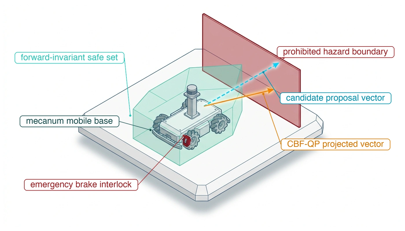
The central constraint is that the learned proposer can neither be trusted with that decision nor be discarded. Its competence is what makes the machine useful, yet nothing in its output bounds stopping distance, actuator effort, or timing. Enforcement resolves the tension by separating proposal from permission, the third law (principle 3), and by giving the permission side three jobs. It must hold a stopping reservation, the clearance the machine needs to arrest its motion from the current state; it must correct a proposal minimally when a feasible correction exists; and it must select a response it can execute without the proposer when none does. The chapter builds the three jobs in that order.
On the warehouse mobile manipulator, the safety microcontroller (MCU) admits the run down the aisle only after the matched stop suffix named in its trajectory record is resident in the MCU’s memory and feasible from the commitment entry state defined in Replacement deadlines and commitment cutoffs. Commitment is the instant after which the machine can no longer abandon the plan’s motion without that latched suffix, so the suffix is matched to the state the machine will have at that instant, not to the states it passes through on the way. Before commitment, a different response must cover the motion. Admission requires an independently executable, state-matched fallback from every state reachable up to that instant. It also requires a bounded representation of the S-curve suffix that the MCU can decode, validate, and execute within its declared workload (the polynomial layout of Trajectory payload is an illustrative encoding rather than that S-curve representation). Because that admission step checks the plan only once before motion starts, the machine still executes the plan one millisecond tick at a time, and enforcement is the check made on every one of those ticks together with the response it selects when even the resident stop no longer fits.
↩︎ The trajectory record and the matched stop suffix it names are established in The Trajectory Record.
The enforcer, the permission path’s per-tick gatekeeper, sits on the permission side of the proposal boundary. It is a hard real-time component that evaluates candidate proposals, verifies invariant state bounds, and holds the exclusive hardware authority to permit current flow or command a fallback stop, keeping the task competence of learned policies while denying them authority over geometric clearance, thermal limits, and human-safety invariants.
↩︎ The per-tick permission cadence on which the enforcer runs is established in Physical time constants and sampling phase lag.
 Enforcement sits on the Plan-to-Act edge: no proposal reaches a drive unchecked.
In the architecture this chapter follows, the enforcer executes on a dedicated microcontroller wired to the sensing and drive interfaces it needs. It checks each candidate command before the drive can apply it. A packet firewall offers a limited software analogy: a sender may request an operation without having authority to perform it. Unlike a packet filter, the enforcer must also account for momentum already present in the plant and preserve an achievable response when it refuses a request.
↪ The silicon placement that keeps the permission path independent of the proposer is developed in Silicon Isolation Decisions.
1 Simplex Architecture: The design came from Carnegie Mellon in the 1990s as a way to upgrade the controller of a running plant without stopping it. An untested new controller drove the plant while a simple verified controller and a switching rule stood ready to take it back (Seto et al. 1998). The learned proposer occupies the untested controller’s seat, and the design’s premise, that the region from which the verified controller can still recover is known in advance, is the stopping envelope this chapter computes.
Seto, Danbing, Bruce Krogh, Lui Sha, and Alongkrit Chutinan. 1998. “The Simplex Architecture for Safe Online Control System Upgrades.” Proceedings of the 1998 American Control Conference (ACC) 6: 3504–8. https://doi.org/10.1109/ACC.1998.703255.
The architecture separates a capable proposer, a resident protective controller, and an output selector. This is the Simplex architecture1 (Seto et al. 1998; Sha 2001), the runtime-assurance pattern that The Machine in Five Levels first named. The proposer supplies useful candidates, while the permission path retains the exclusive ability to select a physically feasible response without waiting for it.
The rest of the chapter follows the running machine through that per-tick check. The starting point is the deficit planning left open, when the jerk-limited stop carried the base’s stopping budget past the rack-end clearance at the drive limit while the body’s departure from its reference remained unpriced: the first quantity the enforcer needs is how far the body can stray from the reference it is asked to follow, because every clearance the permission path defends must also contain that error. Once the tracking bound supplies that missing spatial term, the finished stopping budget fixes the reservation and a candidate aisle speed that still requires physical qualification. Actuator saturation then reveals how quickly that reservation shrinks once gravity or thermal limits spend braking authority. A control barrier function turns the reservation into a constraint on the next command. A least-change filter can then correct a violating proposal, both in free space and in contact, inside a declared cycle budget on a processor the proposer cannot preempt. When a check fails or a lease expires, the fallback hierarchy supplies the surviving hardware response, and the chapter closes with the infrastructure failures that break these premises and the enforcement record that binds every check to its evidence.
Even when communication latency is zero and the permission path admits every reference command without delay, physical robots follow reference trajectories imperfectly. Mechanical compliance, inertia, and non-ideal motor dynamics produce tracking discrepancies. The feedback tracker, the closed-loop controller that turns admitted references into actuator effort, must bound this deviation across the entire maneuver. The bound is a worst-case tracking error tube (\(\TrackingErrorBound\)), an upper bound on the spatial departure of the tracked position output from its nominal reference. For Cartesian point tracking, \(\CartesianPosition(\TimeInstant)\) and \(\ReferencePosition(\TimeInstant)\) denote the actual and reference positions evaluated in the same spatial frame. For whole-body systems such as mobile manipulators, the execution stack defines a declared output map or metric weighting that bounds the maximum physical swept-volume displacement in meters. The safety enforcer depends directly on this bound. Any spatial clearance reserved around a planned reference path must guarantee physical containment of the actual robot body.
↩︎ The admitted setpoints and feedforward torques that the tracker turns into actuator effort are established in The Planning Handoff and the Trajectory Record.
Provided that the physical system begins within an initial qualified error region and its operating parameters (reference velocity, command acceleration, payload mass, external disturbances, and actuator temperature) stay within their validated operating envelope, the feedback controller guarantees the transient position-error bound: \[\|\CartesianPosition(\TimeInstant) - \ReferencePosition(\TimeInstant)\| \le \TrackingErrorBound \quad \forall \TimeInstant \ge 0.\] This guarantee forms a software contract between the tracking layer and the safety enforcer. Rather than re-analyzing raw plant dynamics or reconstructing low-level controller state on every millisecond control cycle, the enforcer consumes this certified error bound as an invariant. However, this contract confines physical motion to the \(\TrackingErrorBound\) tube only while the operational conditions used to establish the certificate remain valid.
The magnitude of \(\TrackingErrorBound\) is a physical distance dictated by hardware properties: reflected rotor inertia (\(\GearReductionRatio^2 \RotorInertia\)), gearbox backlash, structural compliance, and actuator torque saturation. While a steady-state stiffness calculation balances constant external disturbances against closed-loop restoring force, steady-state metrics fail to capture transient overshoot, phase lag, or settling oscillations excited during aggressive maneuvers. Consequently, engineering teams cannot rely on static linear approximations; they must support the tracking tube bound \(\TrackingErrorBound\) with a bounded plant and controller model, defined operating limits, and full-envelope dynamic qualification tests. Tests can expose an invalid bound; the tested trajectories alone do not prove containment for every admissible maneuver.
↩︎ Reflected rotor inertia, \(\GearReductionRatio^2 \RotorInertia\), is established in Reflected rotor inertia and optimal inertia matching.
For the baseline warehouse mobile manipulator, the illustrative dynamic qualification target is \(\TrackingErrorBound =\) 40 mm (illustrative; see the Reader Guide). The tracking controller sustains this bound only while three coupled operational constraints remain satisfied. First, reference trajectories must not demand accelerations exceeding drive torque limits. Second, external disturbance forces must remain below \(\DisturbanceForceBound\), the qualified bound on external disturbance force. Last, actuator coils must operate below their continuous thermal derating thresholds and DC bus voltage limits. A reference trajectory demanding acceleration beyond peak torque drives the actuators into saturation, causing the physical chassis to lag behind the command. Without aggressive anti-windup clamping, the integrator state accumulates severe windup, prolonging recovery long after the reference demand subsides. Outside this qualified operating envelope, the tracking certificate is void, and the system loses its guaranteed error bound.
↩︎ Continuous thermal derating of motor windings is established in Thermal Duty Cycles.
Because the physical robot can deviate from its planned reference by up to \(\TrackingErrorBound\) in any direction, the safety architecture must subtract this uncertainty margin directly from the admissible workspace. Let \(\BarrierFunction\) measure the spatial clearance remaining around a reference. To guarantee that the physical robot maintains non-negative clearance, the enforcer applies an inset contraction: \[\ContractedBarrierFunction(\ReferencePosition) = \BarrierFunction(\ReferencePosition) - \TrackingErrorBound \ge 0.\] A reference trajectory that maintains nominal clearance \(\NominalReferenceClearance\) from a warehouse rack upright guarantees the physical chassis only \(\NominalReferenceClearance - \TrackingErrorBound\) of actual clearance. Consequently, the safety enforcer evaluates reference commands against a contracted boundary that adds 40 mm to the nominal buffer. As detailed in section 12.2, this tracking inset compounds directly with stopping distance budgets, where localization uncertainty and transport delay consume additional clearance. Mechanical wear poses an insidious operational risk here. If worn drive bearings, tire degradation, or altered motor parameters double the true tracking error to 80 mm without updating the enforcer’s parameter registry, the physical base consumes an unbudgeted 40 mm of clearance that the enforcer assumes remains available. An unmodeled tracking degradation silently undermines every higher-level safety margin.
↩︎ Clearance insets that absorb spatial sensing error are established in Spatial Error and Clearance Bounds.
To maintain safety guarantees in production, the runtime monitoring stack must treat \(\TrackingErrorBound\) as an actively verified contract rather than a static design assumption. The underlying real-time middleware publishes \(\TrackingErrorBound\) alongside its validity envelope, while hardware monitors estimate the instantaneous tracking error \(\TrackingErrorDistance(\TimeInstant) = \|\CartesianPosition(\TimeInstant) - \ReferencePosition(\TimeInstant)\|\) on every 1 ms controller tick. Agreement with encoder-reported position is a runtime proxy, not independent evidence of physical localization; the localization allowance must contain drift that these channels cannot expose. If an observable disturbance or actuator thermal throttling causes the monitored \(\TrackingErrorDistance(\TimeInstant)\) to exceed \(\TrackingErrorBound\), the tracking contract is broken. Upon detecting this violation, the safety enforcer revokes the admitted command and activates a state-matched emergency fallback maneuver. Maintaining physical containment during this transition requires that the fallback braking trajectory remains dynamically feasible even after the tracking bound is lost.
Systems Perspective 12.1: The inset margin invariant
A spatial stopping boundary must reserve margin for the tracking loop’s qualified error bound. The runtime stopping envelope (equation 1) incorporates this geometric inset alongside displacement accumulated during transport lag before admitting reference trajectories. When the safety barrier certificates of section 12.4 are formulated in non-spatial coordinates (such as energy or momentum limits), the safety layer must map the tracking tube into a corresponding conservative bound on barrier variation, rather than subtracting a scalar distance. Evaluating barrier certificates against nominal trajectory geometry alone risks admitting references whose physical tracking tubes intersect obstacle boundaries.
Control theory provides rich methodologies for synthesizing tracking controllers, state observers, and disturbance rejection algorithms (Slotine and Li 1991; Åström and Murray 2021). In embedded industrial robotics, systems frequently deploy a cascaded control hierarchy, where outer position loops feed intermediate velocity setpoints down to high-rate current loops. Alternatively, a tracking Model Predictive Controller (MPC) solves an online optimization problem over a receding horizon to generate optimal corrective control actions while respecting actuator bounds. From the perspective of the safety enforcer, the specific internal architecture of the tracking controller is abstracted away; the safety filter requires only that the chosen implementation certifies and guarantees a concrete tracking bound \(\TrackingErrorBound\) under specified operational conditions.
Slotine, Jean-Jacques E, and Weiping Li. 1991. Applied Nonlinear Control. Prentice Hall.
2 Control Lyapunov Function: A Lyapunov function certifies that an unforced system settles; a control Lyapunov function asks only that, at each state, some admissible input make it decrease. Artstein (1983) tied the existence of such a function to stabilizability by feedback, and Sontag (1989) gave an explicit formula that builds the stabilizing input from it. The control barrier function, defined later in this chapter, is its mirror image, keeping the state out of a region instead of pulling it toward a point, and when the two conflict the combined optimization relaxes convergence so that the barrier holds.
Artstein, Zvi. 1983. “Stabilization with Relaxed Controls.” Nonlinear Analysis: Theory, Methods & Applications 7 (11): 1163–73. https://doi.org/10.1016/0362-546X(83)90049-4.
Sontag, Eduardo D. 1989. “A ‘Universal’ Construction of Artstein’s Theorem on Nonlinear Stabilization.” Systems & Control Letters 13 (2): 117–23. https://doi.org/10.1016/0167-6911(89)90028-5.
A tracking controller may establish convergence to the reference path under its qualified model and operating conditions. That result supplies no collision-avoidance guarantee. A well-tuned tracker will follow an erroneous trajectory directly into a warehouse support column with high precision. Control Lyapunov functions2 mathematically formalize this asymptotic convergence toward reference targets; Control Lyapunov functions and stabilization details their theoretical foundation and how optimization pipelines unify stabilizing Lyapunov objectives with the safety barrier certificates this chapter develops in section 12.4.
This division of responsibilities cleanly separates trajectory tracking from safety enforcement. The low-level tracking controller focuses on driving the physical plant toward reference states, while the safety enforcer determines whether those references can be executed without violating invariant boundaries. The tracking error bound \(\TrackingErrorBound\) bridges these subsystems by quantifying the spatial divergence between admitted commands and physical execution. Because environmental disturbances, unmodeled payload shifts, or thermal current derating can rapidly widen this error tube, safety architectures must continuously verify physical performance against contracted assumptions. The downstream stopping envelope accounts for this tracking tube alongside sensor latency, braking distance, and localization drift, ensuring that the physical robot remains safely buffered from surrounding hazards.
12.2 Stopping Envelopes
If the warehouse mobile manipulator approaches a rack end at its 1.5 m/s mechanical drive limit when a coworker steps into the aisle, the delay before braking begins and the jerk-limited deceleration curve carry the base past the 1.10 m clearance even before tracking error is counted. That rack-end crossing is the scene in which nearly every chapter since The Physical Body has priced one stopping term: the body supplied braking and its fixed allowances, the Nervous System the lease path, perception the observation age, and planning the jerk-limited stop suffix that exceeded the rack-end clearance at the drive limit (Base stopping budget under jerk-limited deceleration). The tracking bound of The Tracker Handoff and Dynamic Reference Envelopes is the last spatial term. Every one of these terms serves the test that the first law, irreversibility (principle 1), sets, \(\StoppingDistance \le \ClearDistance\). The enforcer applies that test not as one calculation but as a set of states.
Definition 12.1: Stopping envelope
Stopping envelope is the set of plant states, parameterized by clearance and velocity along each degree of freedom, from which the resident emergency braking response, initiated after accounting for all worst-case delays, halts motion before reaching an obstacle boundary while preserving all localization, protective, and tracking margins.
- Significance: The envelope translates the abstract irreversibility requirement \(\StoppingDistance \le \ClearDistance\) into an actionable runtime velocity ceiling. When approaching a rack end, the warehouse mobile manipulator’s envelope restricts forward velocity, with the stated dispatch allocation, to at most 1.35 m/s, substantially below its mechanical drive limit of 1.5 m/s.
- Distinction: Unlike a static geometric keep-out zone that depends solely on position, the stopping envelope is a dynamic construct governed by speed, system latencies, and braking authority. A given physical clearance safely admits a slow approach while strictly forbidding a high-speed transit.
- Common pitfall: Treating the stopping envelope as a static, precomputed boundary. In practice, carried payload mass, surface traction coefficients, and motor thermal limits continuously reshape this boundary; calculating safety margins from ideal datasheet decelerations severely overestimates stopping authority when the machine is heavily loaded.
The stopping envelope is the machine’s recoverable set, the states from which the resident stop still succeeds. Inevitable collision states fixes the same boundary in time, as the commitment deadline past which momentum can carry the machine into an inevitable collision state. Velocity enters the recoverable set twice. Delay travel grows linearly with speed and braking travel quadratically, so a clearance that admits a slow approach forbids a fast one at the same position, and the enforcer must keep the machine inside the envelope on every tick, before a fault or an unmodeled disturbance can carry it out. The running calculation uses representative engineering limits; deployment requires each term to be qualified on the actual hardware.
The pre-brake delay \(\PrebrakeDelay\) of Kinematic stopping distance and pre-brake delay already contains the enforcer’s permission cycle, budgeted alongside the lease communication path in Chunk Lease Sizing from the Stopping Budget. One interval stays out of the spatial sum: the dispatch-to-admission delay \(\DispatchAdmissionInterval\), which The capture-to-brake-onset timing budget of the running machine places between proposal dispatch and admission. The budget charges it instead against the timing allowance that the remaining clearance leaves (section 12.2.1). What the spatial sum still lacks is the tracking error between the commanded reference and the actual plant.
The enforcer accounts for that error with the tracking bound \(\TrackingErrorBound\), offsetting the baseline stopping distance of equation 2.2. It can admit a candidate reference trajectory only if the plant, which may lag that reference by up to \(\TrackingErrorBound\), can still brake to a standstill within the available free distance \(\ClearDistance\). Combining physical clearance, latency, and velocity yields the stopping subtotal before dispatch-to-admission travel is charged: \[\SpeedAtDetection\,\PrebrakeDelay + \ResidentStopDistance(\SpeedAtDetection) + \LocalizationBound + \ProtectiveClearanceMargin + \TrackingErrorBound \le \ClearDistance \tag{1}\] Here, \(\ResidentStopDistance(\SpeedAtDetection)\) represents the physical distance traversed during the braking maneuver from an initial speed \(\SpeedAtDetection\). For idealized constant-deceleration braking, this term simplifies to \(\SpeedAtDetection^2 / (2\CredibleBrakingDeceleration)\). Under realistic jerk-limited trajectory profiles, \(\ResidentStopDistance(\SpeedAtDetection)\) is governed by equation 11.17, which incorporates the additional displacement accrued during finite jerk transitions. The term \(\LocalizationBound\) denotes the localization uncertainty bound, while \(\ProtectiveClearanceMargin\) provides an explicit protective safety cushion. The left-hand side sums the baseline stopping distance \(\StoppingDistance(\SpeedAtDetection)\) from equation 2.2 with the tracking inset \(\TrackingErrorBound\).
↪ The full stopping-distance model, tracking inset included, is developed in Kinematic Stopping Envelopes and Information Age Lag.
For complete static-obstacle admission, the delay term uses \(\PrebrakeDelay + \DispatchAdmissionInterval\) in place of \(\PrebrakeDelay\); the resident stop and fixed allowances are unchanged. This inequality defines a conditional stopping subtotal in state space. Within this set, the accounted reaction latency and braking profile fit within the measured obstacle clearance; complete admission must also charge dispatch-to-admission travel. Operating outside this boundary violates the stopping reservation under the qualified model assumptions, though conservative engineering margins do not imply that an instantaneous collision is certain under all conceivable emergency maneuvers. Per-tick enforcement must maintain this stopping reservation over the entire control epoch until the next validated command can take effect, rather than merely verifying instantaneous feasibility at the sample instant.
Whenever a proposed trajectory requires a stopping distance in equation 1 that exceeds the measured clearance along the current heading, the enforcer rejects the command. Because the robot moves directionally, the stopping envelope is anisotropic. Heading dictates which obstacles threaten forward travel and consume braking clearance, while localization uncertainty and the robot’s swept geometric volume demand clearance margins around the entire perimeter.
12.2.1 Sizing the composite stopping budget
Omitting any single interval during which the base keeps moving before or during a stop, or evaluating those intervals under mismatched operating conditions, admits transit speeds that overrun the physical boundary when all delays coincide. The composite stopping budget therefore reserves clearance for every interval in the arrest sequence: sensor transduction lag, compute scheduling delays, actuator engagement, the deceleration profile, and tracking divergence, each evaluated under the same worst-case operating conditions.
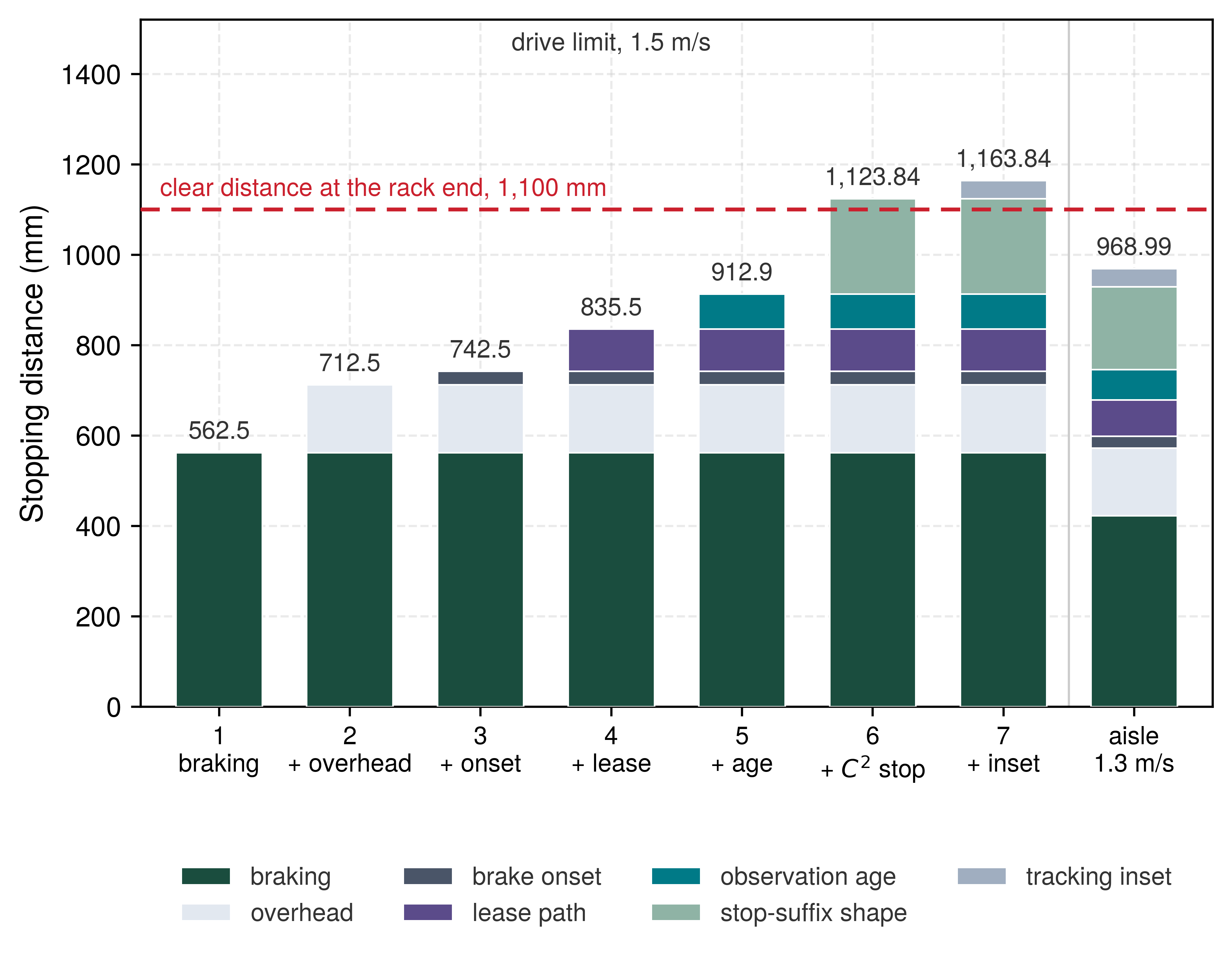
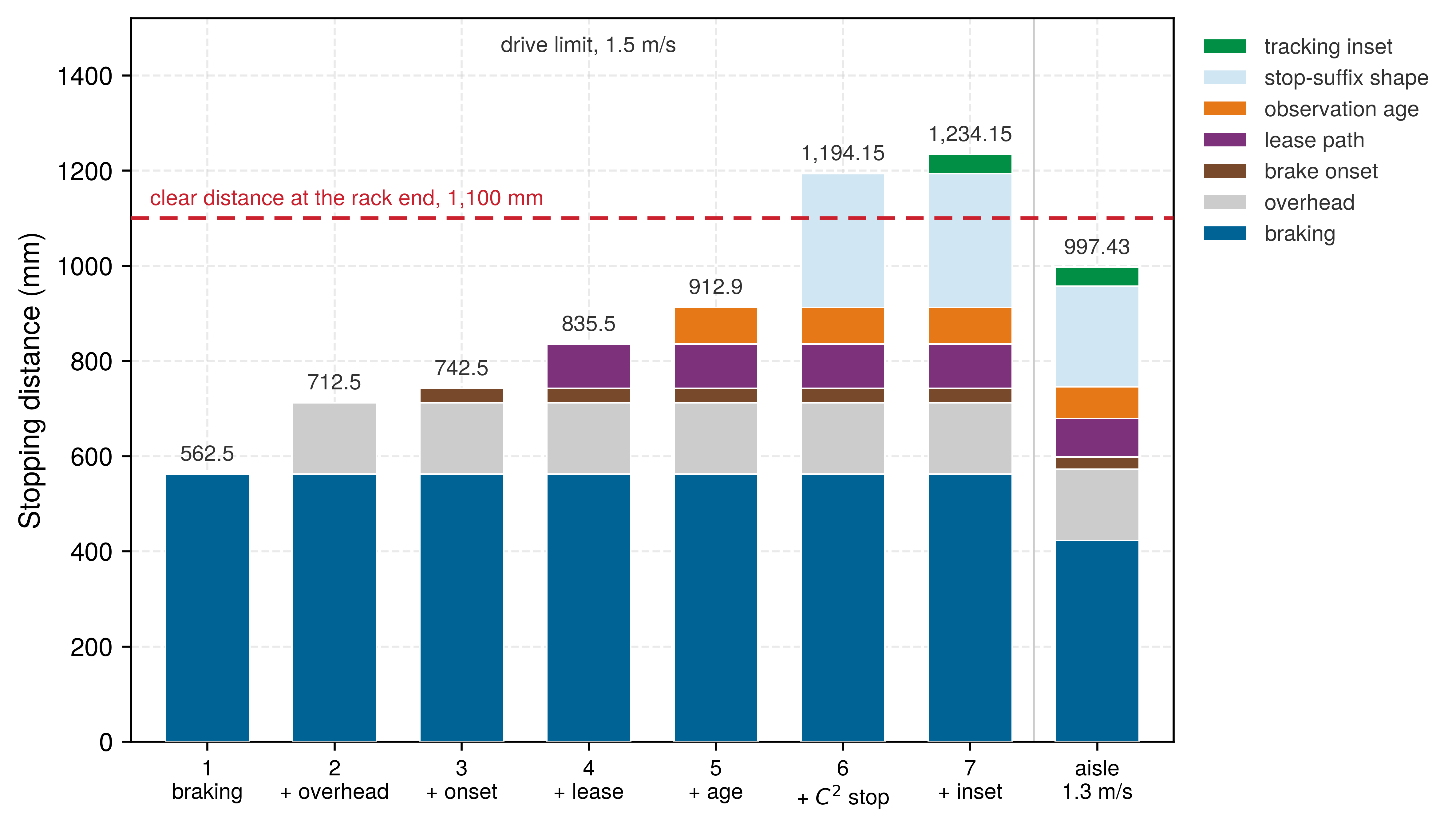
For the warehouse mobile manipulator, the tracking bound of 40 mm is the final spatial term. At the 1.5 m/s drive limit, the matched stop suffix had already pushed the cumulative requirement to 1,123.84 mm, past the 1.10 m rack-end clearance; that is the deficit Base stopping budget under jerk-limited deceleration left open. The tracking inset carries the total to 1,163.84 mm, an overshoot of 63.84 mm beyond the physical boundary.
The \(\DifferentiabilityClass^2\) stop suffix replaces idealized constant deceleration (\(\SpeedAtDetection^2 / 2\CredibleBrakingDeceleration\)) with the jerk-limited S-curve of The C^2 stopping suffix and jerk-limited braking, governed by the peak jerk limit \(\JerkLimit =\) 7.11 m/s³. Planning stipulated that bound from the reference \(\DifferentiabilityClass^2\) polynomial rather than measuring it; the S-curve is the stop the MCU actually runs, and the polynomial supplies only its jerk bound. Because both operating velocities reach the peak deceleration threshold, equation 11.17 models this maneuver by adding the displacement of half a jerk ramp: \[\ResidentStopDistance(\SpeedAtDetection) = \frac{\SpeedAtDetection^2}{2 \CredibleBrakingDeceleration} + \SpeedAtDetection\,\frac{\CredibleBrakingDeceleration}{2 \JerkLimit}.\] Because this smoothly shaped stop consumes more clearance than discontinuous full-torque braking, the admissible transit speed must be read from the finished budget rather than from the constant-deceleration estimate.
Velocity remains the single operational variable the control architecture can dynamically modulate. Above the characteristic velocity threshold \(\CredibleBrakingDeceleration^2/\JerkLimit =\) 0.56 m/s, the finite jerk ramps function equivalently to an added delay of \(\CredibleBrakingDeceleration/(2\JerkLimit)\) prior to braking at constant deceleration \(\CredibleBrakingDeceleration\). Under these conditions, the pre-dispatch speed ceiling keeps the form of equation 2.3, the positive root of the stopping inequality at equality. The jerk ramps lengthen the pre-brake delay to an effective delay, and the tracking bound comes off the available braking distance: \[\SpeedBound = -\CredibleBrakingDeceleration{}\EffectiveBrakingDelay + \sqrt{(\CredibleBrakingDeceleration{}\EffectiveBrakingDelay)^2 + 2\CredibleBrakingDeceleration{}\InsetAvailableBrakingDistance}, \qquad \EffectiveBrakingDelay = \PrebrakeDelay + \frac{\CredibleBrakingDeceleration}{2\JerkLimit}, \qquad \InsetAvailableBrakingDistance = \ClearDistance - \LocalizationBound - \ProtectiveClearanceMargin - \TrackingErrorBound \tag{2}\] Below \(\CredibleBrakingDeceleration^2/\JerkLimit\), the deceleration trajectory never reaches the peak limit \(\CredibleBrakingDeceleration\), rendering stopping distance non-quadratic in velocity; in this low-speed regime, MLSysIM evaluates equation 1 via numerical root-finding. Notebook 12.1 computes this ceiling for the mobile manipulator approaching the aisle rack end.
Napkin Math 12.1: The ceiling the budget sets
Problem: The warehouse mobile manipulator approaches the rack end with rows 1 to 7 of table 1 accounted, before dispatch-to-admission travel. What is the highest speed at which the jerk-limited stop still fits the clear distance, and how much clearance does a candidate aisle speed of 1.3 m/s leave?
Variables:
- \(\ClearDistance =\) 1.10 m (Illustrative; clear distance at the rack end).
- \(\LocalizationBound + \ProtectiveClearanceMargin =\) 50 mm \(+\) 100 mm (Illustrative localization bound; chosen protective clearance), and \(\TrackingErrorBound =\) 40 mm (Illustrative; the qualification target of The Tracker Handoff and Dynamic Reference Envelopes).
- \(\CredibleBrakingDeceleration =\) 2 m/s² (Illustrative; credible loaded deceleration on a dry floor) and \(\JerkLimit =\) 7.11 m/s³ (Derived; the peak jerk of the reference \(\DifferentiabilityClass^2\) polynomial).
- \(\PrebrakeDelay =\) 133.6 ms (Derived; observation age plus lease path plus brake onset, excluding \(\DispatchAdmissionInterval\)).
- Drive limit 1.5 m/s (Illustrative).
Math: The fixed allowances leave \(\InsetAvailableBrakingDistance =\) 1,100 mm \(-\) 190 mm \(=\) 910 mm. The jerk ramps lengthen the delay to \(\EffectiveBrakingDelay =\) 133.6 ms \(+\) 140.6 ms \(=\) 274.2 ms, so \(\CredibleBrakingDeceleration{}\EffectiveBrakingDelay =\) 0.5485 m/s. Under the square root of equation 2, \((\CredibleBrakingDeceleration{}\EffectiveBrakingDelay)^2 =\) 0.3008 and \(2\CredibleBrakingDeceleration{}\InsetAvailableBrakingDistance =\) 3.64 (both in m²/s²), whose sum has root 1.9851 m/s; subtracting 0.5485 m/s gives the ceiling. At 1.3 m/s the terms of table 1 sum to 969.0 mm, and the remainder divided by the speed is the timing allowance.
Result: The pre-dispatch ceiling is \(\SpeedBound =\) 1.44 m/s, below the 1.5 m/s drive limit. The candidate aisle speed leaves 131.0 mm of spare, equivalent to 100.8 ms of unallocated delay.
Systems insight: The irreversibility requirement \(\StoppingDistance \le \ClearDistance\), rather than motor electrical capability, dictates the operating speed. Running at the nominal drive limit violates the verified spatial budget, and the speed ceiling shifts strictly through the parameters governing the quadratic root and effective latency \(\EffectiveBrakingDelay\): available clearance, qualified braking deceleration, fixed margins, and end-to-end transport lag. Any latency introduced by downstream processing directly consumes the 100.8 ms timing allowance, which cannot be arbitrarily replenished.
The candidate transit speed, 1.3 m/s, sits below that ceiling, and its 131.0 mm margin is the only clearance left to absorb unmodeled pipeline delays or to serve as a reserve. That margin is narrow relative to the failure modes it must absorb. If chunk lease enforcement were entrusted to a non-real-time host operating system, an upstream planning stall lasting 200 ms instead of the nominal 60 ms lease would inject 182 mm of unbraked displacement, causing the base to overrun the rack clearance by 50.99 mm. This hazard shows why lease termination must be autonomously enforced by dedicated microcontroller hardware directly gating motor power (section 12.5).
The observation-age term ends at dispatch, and the chunk lease begins at admission, so the interval between them, \(\DispatchAdmissionInterval\), belongs to neither. The complete operational delay therefore expands to \(\AdmissionInclusivePrebrakeDelay = \PrebrakeDelay + \DispatchAdmissionInterval\), requiring an additional spatial reservation of \(\SpeedAtDetection\DispatchAdmissionInterval\). This phase encompasses any remaining neural inference, safety envelope projection, and inter-process communication; pipelined or overlapping stages must be budgeted carefully to avoid double-counting. A newly arrived sensor observation updates this budget only when the hardware pipeline delivers and validates it prior to actuation. Laid out on one time axis (figure 2), the observation age ends at dispatch, the dispatch-to-admission interval follows, and the lease, one tick, one bus cycle, and drive onset bring the base to brake onset. A travel row beneath converts each interval into millimeters at the candidate aisle speed.
At this candidate speed, dividing the 131.0 mm spare distance by the speed yields 100.8 ms of unallocated timing allowance. Added to the 51.6 ms observation age, that allowance places the latest admission after capture at 152.4 ms. Added to the 133.6 ms pre-brake delay, it places the latest brake onset after capture at 234.4 ms. The dispatch-to-admission interval spends part of that allowance and leaves whatever remains as the reserve; because operating right at these boundaries spends all available clearance, the figures are qualification constraints rather than performance claims. The budget carries forward the allocation that the placement chapter makes for this interval (The board-link budget and the dispatch-to-admission interval), \(\DispatchAdmissionInterval =\) 63.3 ms for the partitioned compute pipeline. That allocation consumes 82.3 mm of the spatial margin, leaves a cushion of 37.5 ms (48.7 mm of distance), and puts total latency from capture to brake onset at 196.9 ms. Because that allocation is an engineering budget rather than a measurement, an instrumented campaign with hardware timestamps must confirm it before the vehicle can be certified at this speed. Read row by row (table 1, figure 1), the terms through observation age fit inside the clear distance at the 1.5 m/s drive limit, whereas the jerk-limited stop (row 6) carries the total past the line and the tracking inset (row 7) widens the breach. At the 1.3 m/s aisle speed, those same terms stop 131.0 mm short of the line and still leave a 48.7 mm reserve once dispatch-to-admission travel is charged.
| Row | Added in | Term | At drive limit (mm) | Running total (mm) | Left of \(\ClearDistance\) (mm) | At aisle speed (mm) |
|---|---|---|---|---|---|---|
| 1 | Kinetic Momentum | Braking, \(\SpeedAtDetection^2/2\CredibleBrakingDeceleration\) | 562.5 | 562.5 | 537.5 | 422.5 |
| 2 | Kinetic Momentum | Overhead, \(\LocalizationBound+\ProtectiveClearanceMargin\) | 150 | 712.5 | 387.5 | 150 |
| 3 | Kinetic Momentum | Brake onset, \(\SpeedAtDetection\ActuatorResponseTime\) | 30 | 742.5 | 357.5 | 26 |
| — | Two proposers and the evidence horizon | Time only: the chunk policy can renew a lease; the intent model’s 336 ms inference cannot | — | — | — | — |
| 4 | Chunk Lease Sizing from the Stopping Budget | Lease path, \(\SpeedAtDetection(\ChunkLease+\PermissionLoopPeriod+\CommandTransportTime)\) over 62 ms | 93 | 835.5 | 264.5 | 80.6 |
| 5 | The latency waterfall | Observation age, \(\SpeedAtDetection\,\ObservationAge\) over 51.6 ms | 77.4 | 912.9 | 187.1 | 67.08 |
| — | Forward State Propagation and Occlusion Decay | Time only: abreast of an occluded rack end the erosion law of equation 9.13 leaves no free depth, so the free-space claim lasts 0 ms and memory cannot certify it | — | — | — | — |
| 6 | Base stopping budget under jerk-limited deceleration | Jerk-limited \(\DifferentiabilityClass^2\) stop, the jerk-ramp travel \(\SpeedAtDetection\,\CredibleBrakingDeceleration/2\JerkLimit\) added to \(\SpeedAtDetection^2/2\CredibleBrakingDeceleration\) | 210.94 | 1,123.84 | \(-23.84\) | 182.81 |
| 7 | section 12.2 | Tracking inset, \(\TrackingErrorBound\) | 40 | 1,163.84 | \(-63.84\) | 40 |
| Total | 1,163.84 | 968.99 | ||||
| Left of \(\ClearDistance\) | \(-63.84\) | 131.01 | ||||
| 8 | The board-link budget and the dispatch-to-admission interval | Dispatch-to-admission travel, \(\SpeedAtDetection\,\DispatchAdmissionInterval\) over 63.3 ms, charged against the spare at the aisle speed only | — | — | — | 82.3 |
| Reserve after row 8 | — | 48.7 |
This baseline stopping model evaluates a stationary obstacle situated at distance \(\ClearDistance\), such as a dropped warehouse tote or a pedestrian who has stepped out from an aisle rack and stopped. Under this assumption, the hazard remains fixed from the instant braking begins. If, instead, a pedestrian continues walking toward the vehicle throughout the reaction and braking phases, the obstacle actively closes the safety gap from the opposing direction. Before dispatch allocation, an ongoing pedestrian approach restricts the mobile base to a subtotal ceiling of just 0.26 m/s at this rack end.
This drastic velocity reduction occurs because an active hazard penalizes the stopping budget by the duration of the stop rather than merely its displacement. Assuming an ISO 13855 approach velocity \(\HumanWalkingSpeedBound =\) 1.6 m/s across the entire reaction and stopping interval \(\PrebrakeDelay + \StoppingDuration(\SpeedAtDetection)\), the spatial budget acquires an additional closure penalty \(\HumanWalkingSpeedBound\,[\PrebrakeDelay + \StoppingDuration(\SpeedAtDetection)]\) absent from static calculations. When operating below the velocity threshold \(\CredibleBrakingDeceleration^2/\JerkLimit =\) 0.56 m/s, the jerk-limited braking profile cannot achieve peak deceleration \(\CredibleBrakingDeceleration\); it ramps deceleration up and immediately down in a triangular profile lasting \(2\sqrt{\SpeedAtDetection/\JerkLimit}\). This duration diminishes far more slowly than the linear scaling \(\SpeedAtDetection/\CredibleBrakingDeceleration\) as velocity decreases. Initiating a jerk-limited stop from 0.26 m/s requires 382 ms, compared to only 130 ms for idealized step deceleration. While the mobile base travels only 50 mm during braking, the pedestrian advances 612 mm toward the robot over the same window. Achieving peak deceleration from such low speeds would demand a jerk of 41 m/s³, several times the stipulated bound the load was assumed to tolerate, whereas unconstrained step deceleration would permit 0.64 m/s. That contrast arises because the jerk bound costs differently in the two regimes. Above \(\CredibleBrakingDeceleration^2/\JerkLimit\) it adds a fixed delay of \(\CredibleBrakingDeceleration/(2\JerkLimit)\) whose travel grows with speed and forms the row-6 term pushing the drive limit past the clear distance. Below that threshold it stretches the stop’s duration. Against a person who keeps walking, duration is what the budget pays for, so reducing operating speed yields diminishing safety returns.
↩︎ The pedestrian intrusion distance, evaluated for a constant-deceleration stop at the drive limit, is established in Forward State Propagation and Occlusion Decay.
Throttling nominal aisle velocity to the walking-person ceiling would severely degrade warehouse transport throughput for an event that facility layout and procedural crossing rules can prevent. The baseline operational design therefore mandates enforced physical or optical crossing restrictions at aisle ends, while the residual-claims register in A residual-claims register tracks the governing premise that pedestrian incursions into the stopping zone are procedurally prevented. Operating at the candidate aisle velocity remains contingent on empirical validation of these access restrictions. The derivation bounds stopping against a static obstruction; protecting against an unconstrained approaching pedestrian requires certified physical interlocks or external safety scanners.
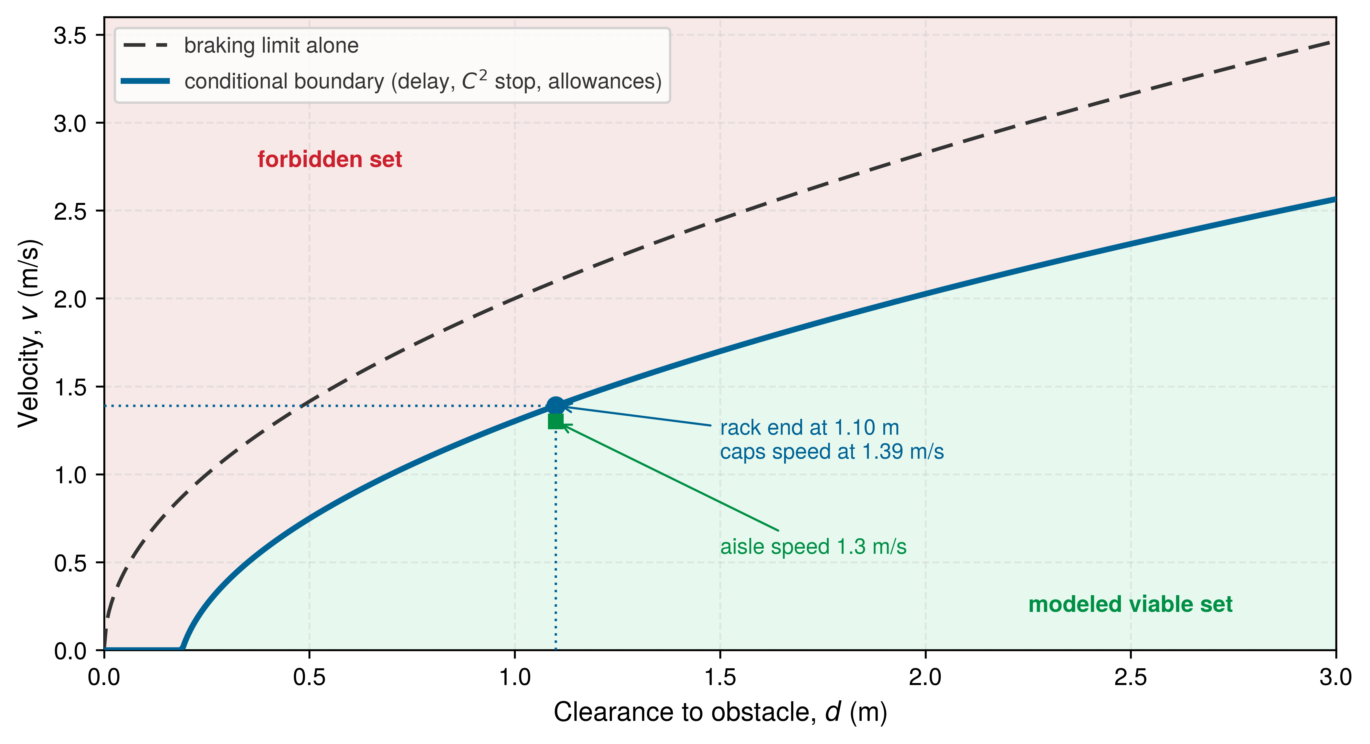
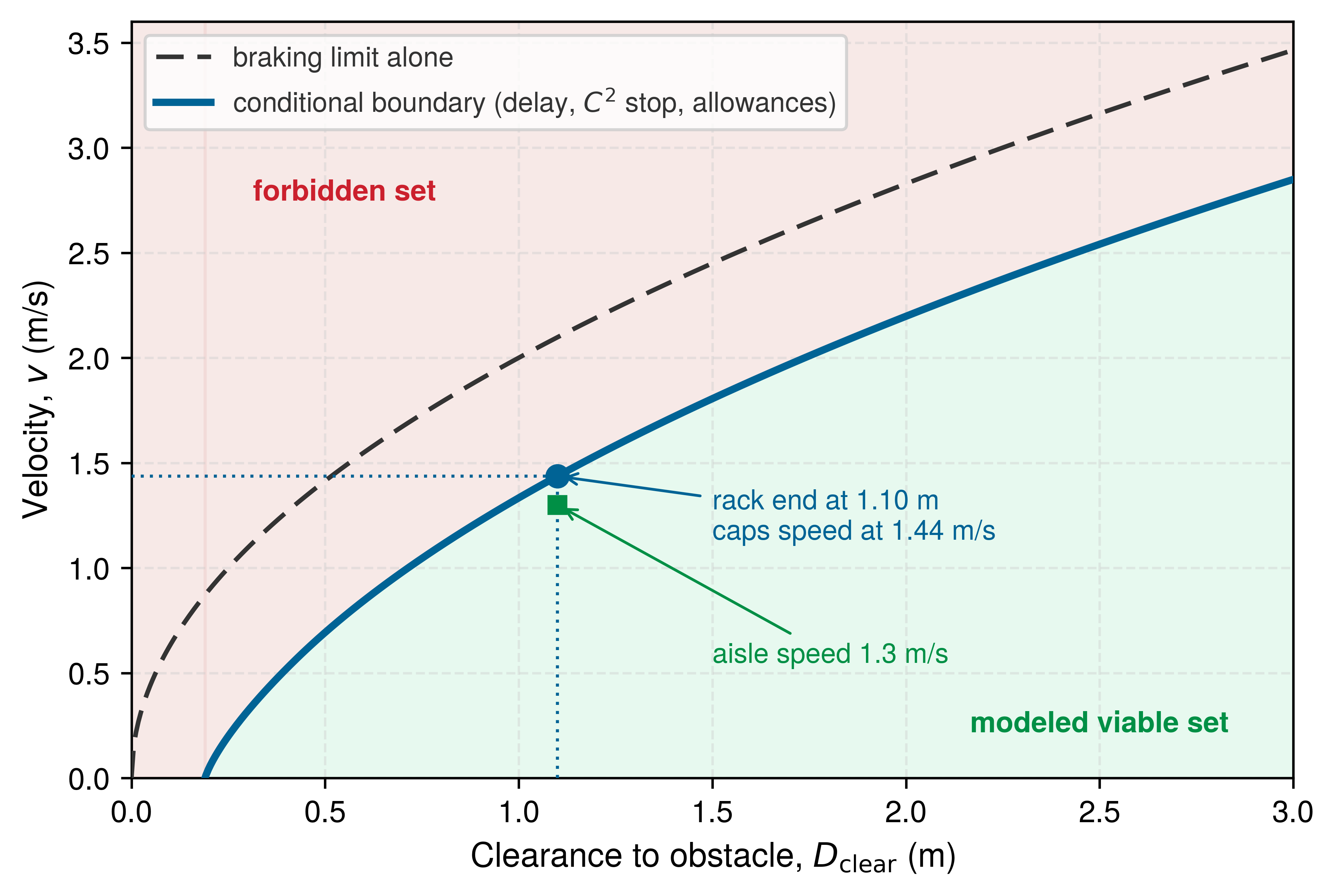
Three operating regimes therefore set three ceilings (figure 3). On a dry floor, fixed allowances, linear delay travel \(\SpeedAtDetection\PrebrakeDelay\), quadratic braking travel \(\SpeedAtDetection^2/(2\CredibleBrakingDeceleration)\), and jerk-ramp travel sum to a total that meets the 1.10 m clear distance at 1.44 m/s. Even an optimistic all-weight traction screen requires a floor friction coefficient of at least 0.204, because \(\TractionLimitedDeceleration = \min(\CredibleBrakingDeceleration, \CoulombFrictionCoefficient \Gravity)\) assumes all weight contributes braking traction. The running machine also requires qualified driven-wheel load share, torque, and stability (Kinetic Momentum). On a sealed floor inspected to \(\CoulombFrictionCoefficient =\) 0.12, the ceiling falls to 1.23 m/s. A pedestrian walking toward the base at 1.6 m/s charges the stop by its duration and contracts the ceiling to 0.26 m/s. Because these three roots are subtotal ceilings before dispatch allocation, charging the 63.3 ms allocation lowers each of them. The dry-floor root falls to 1.35 m/s by adding the base’s travel through dispatch. The optimistic inspected-floor root falls to 1.17 m/s in the same way. The walking-person root falls to 0.19 m/s by adding both the base’s travel and the person’s closure across that interval. Because operating at any maximum root spends all clearance and leaves zero reserve, the remaining reserve must be recomputed for the selected speed, floor, and hazard motion. The 37.5 ms timing reserve belongs specifically to the dry, static-obstacle 1.3 m/s candidate, and an authority transition cannot claim its original 100.8 ms margin a second time.
↪ The authority transitions that must fit inside this remaining reserve are developed in Authority Transitions.
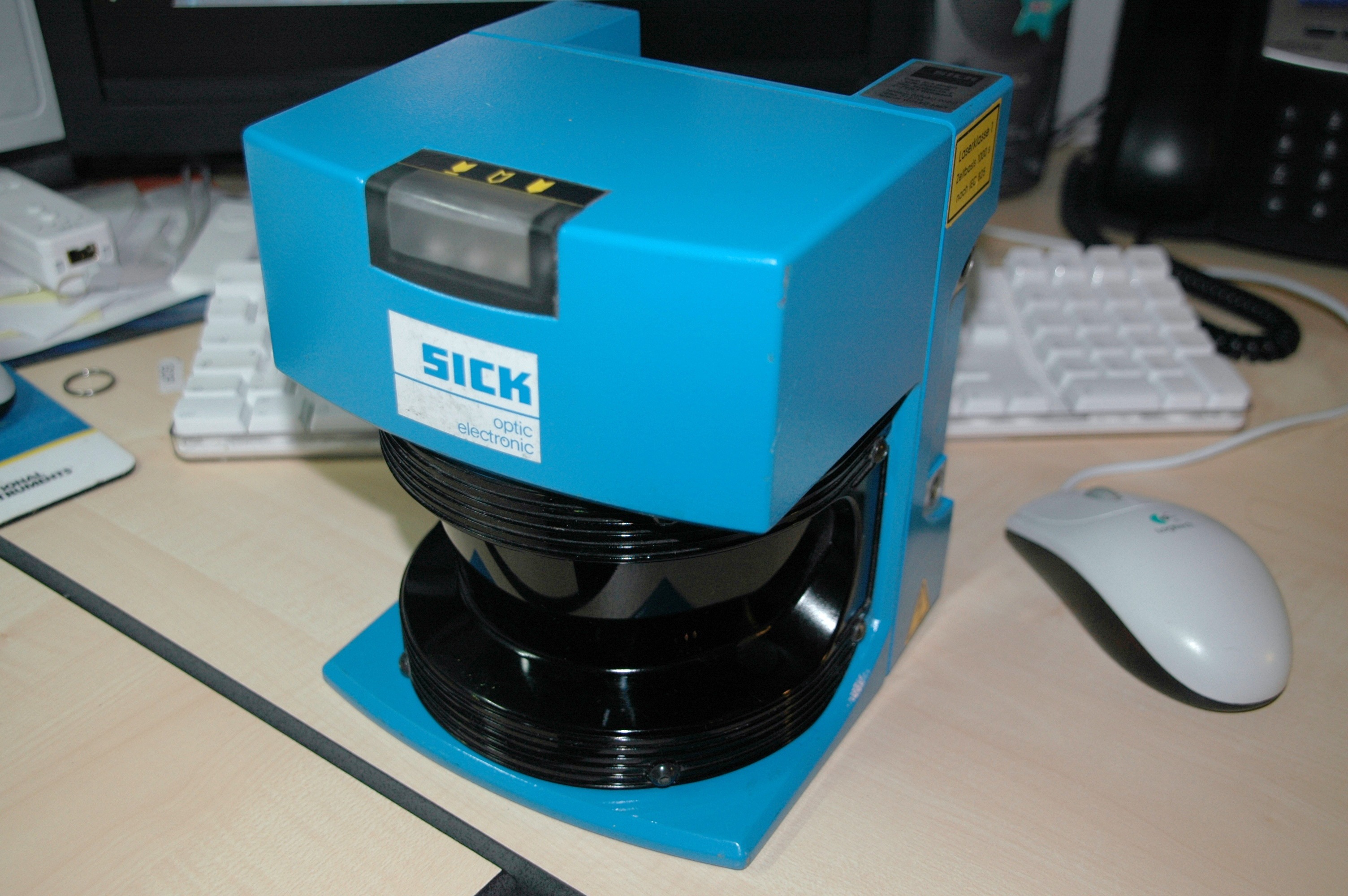
An independent protective safety scanner operates under its own hardware-to-actuation timing budget. When an obstacle breaches a safety-rated zone, the scanner’s internal optical sampling, fail-safe output switching, safety controller logic, and drive disconnect delays entirely bypass the perception dispatch and software lease infrastructure. However, the physical response must still reserve the same underlying deceleration distance, mechanical tracking error, localization tolerance, and protective safety cushion; only computational delays bypassed by the safety bus are eliminated from the sum. Industrial mobile bases deploy such protective fields under ISO 3691-4 (International Organization for Standardization 2023b) for driverless industrial trucks and ISO 13849-1 (International Organization for Standardization 2023a) for safety-related control circuits, using a safety-rated planar scanner of the kind in figure 4, which evaluates programmable warning and protective fields. The physical dimensions of this protective field must be calculated from the dedicated scanner path’s verified hardware timing budget, rather than inheriting the software lease and vision latencies of the neural planner. The safety-rated optical scanner is a component of a separately qualified protective function, distinct from the primary perception LiDAR that generates non-safety-rated point clouds for neural proposal generation. Its component rating does not certify the complete sensor-to-stop path. In the running architecture, that path must establish the detection coverage, response time, and physical stopping performance required for protection at rack intersections. Section 12.8.3 maps the software stopping budget onto this certified hardware baseline and shows that industrial vehicle testing standards validate pedestrian detection against the same static-obstacle assumption derived here.

12.2.2 Phase portraits and speed ceilings
Checking velocity against a fixed scalar limit fails as soon as obstacle distance shrinks: a speed that is recoverable two meters from the rack end becomes an inevitable collision eighty centimeters closer. Drawn in the distance–velocity \((\ClearDistance, \SpeedAtDetection)\) phase plane (figure 5), the plotted pre-dispatch envelope separates states whose accounted subtotal fits from states whose subtotal already exceeds clearance. Complete admission contracts that boundary further by charging dispatch travel. Braking alone traces the outer parabola. The inset boundary pulls the viable set, the recoverable set drawn in this plane, inward by the pre-brake travel \(\SpeedAtDetection\PrebrakeDelay\), the jerk ramps of the matched stop, and the fixed localization, protective, and tracking allowances. At the rack-end clear distance the height of that plotted boundary is the subtotal speed ceiling, with the candidate aisle speed beneath it. The complete dry-floor ceiling is 1.35 m/s; the governor must use the fully charged boundary. Under the verified delay and deceleration bounds, the envelope is therefore a velocity ceiling that varies with clearance, and a state outside it violates the stopping reservation even if an emergency maneuver might avoid a collision in an edge case.
Evaluated on every enforcer tick, the envelope becomes a speed governor that runs in two stages, and their order matters:
- Current-state feasibility check: The enforcer first verifies whether the robot’s current operational state \((\ClearDistance, \SpeedAtDetection)\) remains strictly inside the envelope. It tests whether a full braking response from the current velocity \(\SpeedAtDetection\), with all transport lags, jerk transitions, and margin allowances, fits within the currently measured clearance \(\ClearDistance\). If this condition fails, no newly proposed command setpoint can restore the lost stopping reservation, because reducing the target acceleration cannot retroactively erase the kinetic energy or displacement accrued from the existing physical velocity. A violation at this step immediately selects
STOP, the resident controlled stop that section 12.8 defines among the enforcer’s fallback responses. - Candidate command projection: If and only if the current state passes validation, the enforcer samples the speed ceiling \(\SpeedBound(\ClearDistance)\) from the fully charged counterpart of the pre-dispatch boundary shown in figure 5. It then clamps the candidate velocity proposal \(\CandidateSpeedCommand\) to the admissible ceiling, admitting \(\AdmittedSpeedCommand = \min\bigl(\CandidateSpeedCommand, \max(0, \SpeedBound)\bigr)\). Rather than discarding an over-speed proposal entirely, this governor projects the command onto the boundary of the safe set.
If obstacle clearance shrinks, computational jitter expands end-to-end latency, or floor friction degrades, the envelope boundary shifts inward, throttling admissible velocity on the subsequent control cycle when qualified sensing or configuration evidence exposes the change. A reference clamp alone does not establish that actual velocity remains inside the envelope between checks. This one-dimensional velocity governor is the scalar prototype for multi-dimensional safety filters; in section 12.4, control barrier functions extend this exact principle to enforce forward invariance over full state spaces.
↩︎ The clearance-parameterized velocity ceiling is established as a kinematic constraint in Dynamic velocity ceilings and clearance budgeting.
The stopping envelope is the kinematic roofline of Delay consumes stopping clearance carried through the finished budget. Physical clearance (\(\ClearDistance\)) sets a ceiling on transit speed for the qualified braking, margin, and timing bounds. A faster inference frame rate raises that ceiling only if it reduces a delay charged to the stopping budget. Model size and inference optimizations affect the ceiling through their share of the sensor-to-actuator delay \(\PrebrakeDelay\). On the warehouse mobile manipulator, every 1 ms of added pipeline delay consumes 1.3 mm of spatial clearance at nominal aisle velocity, and an unbudgeted 10 ms latency increase depresses the allowable speed ceiling by approximately 14 mm/s. Consequently, deploying an oversized vision-language model that increases latency directly lowers maximum transit speed, whereas an inference improvement that does not change the scheduled delivery tick may leave the charged delay unchanged. The speed ceiling shifts materially only when altering the physical parameters of the plant: verified deceleration authority \(\CredibleBrakingDeceleration\), end-to-end transport lag \(\PrebrakeDelay\), tracking error bound \(\TrackingErrorBound\), and localization uncertainty \(\LocalizationBound\).
None of these governing parameters remain stationary during real-world operation. Manipulating a heavy payload in the end-effector increases arm inertia, diminishing joint deceleration limits within peak motor torque bounds. Industrial floor contaminants such as oil or water severely degrade tire traction beneath the assumed braking limit \(\CredibleBrakingDeceleration\), while aggressive operational cycles heat motor windings and drive inverters into thermal derating. A safety enforcer that treats \(\CredibleBrakingDeceleration\) as an immutable datasheet constant will dangerously underestimate stopping distance under heavy workloads. Runtime safety monitors must update braking bounds as observable, qualified payload and thermal states evolve. Instantaneous wheel-floor friction is not measured on this machine; an unobserved floor change invalidates the inspection premise and requires an operating restriction rather than automatic adaptation. In either case, relying on unvalidated, optimistic estimates invalidates the formal safety contract.
Dynamic adaptation remains effective only as long as state estimators remain uncorrupted and physical actuators retain control authority. If severe surface contamination reduces friction toward zero, or if sustained high-torque demands push drive inverters beyond their thermal trip thresholds, physical braking authority collapses. When required stopping torque exceeds what the physical hardware can exert against the environment, software can still detect the boundary violation, but it can no longer prevent an impact.
12.3 Authority Exhaustion and Emergency Fallback
A loaded arm descending toward the packing station must counter gravity before any torque remains to slow its motion. Actuator saturation occurs when requested effort reaches the electrical, mechanical, or thermal limits of the physical body, which can cause downstream integral controllers to accumulate windup.3 The actuator cannot deliver the corrective control action \(\CertifiedControlAction\) at its commanded magnitude in any of several cases. Motor phase currents may hit inverter current-chopping limits (\(\InverterCurrentLimit\)). The DC bus may sag under inductive switching transients (\(\PowerRailInductance\,d\ConductorCurrent/d\TimeInstant\)). Back-EMF at high rotor speeds may collapse voltage headroom (\(\DcRailVoltage - \MotorBackEmfConstant \RotorAngularSpeed \to 0\)). Winding temperatures may approach thermal derating thresholds (\(\WindingTemperature \to \WindingTemperatureLimit\)). No mathematical safety boundary can be defended with control effort the physical body cannot generate.
3 Integrator Windup: A proportional-integral controller’s integral term continues summing tracking error while an actuator sits at its saturation limit, as standard feedback loops do not inherently know that command outputs are clipped. When tracking error reverses, this accumulated state must unwind before the actuator command can leave the saturation rail. That unwinding delay directly consumes safety clearance. While modern anti-windup schemes clamp or back-calculate integrator state during saturation (Åström and Murray 2021), the safety enforcer must still budget whatever residual unwinding delay remains in the low-level hardware controller.
Åström, Karl Johan, and Richard M Murray. 2021. Feedback Systems: An Introduction for Scientists and Engineers. Princeton university press.
↩︎ The electrical and transmission limits that bound delivered actuator effort are established in Actuator Transmission Limits.
When required braking effort exceeds physical actuator limits, no safety filter can enforce the promised stopping horizon. An emergency fallback invoked after control authority is lost can mitigate damage, but it cannot restore an invariant guarantee that physical dynamics have already broken. The runtime enforcer must therefore contract its forward reservation before actuator effort saturates, preserving a feasible braking margin under worst-case loading.
A stopping envelope based on peak torque alone overstates braking authority when gravity drives the moving load toward a hazard. Under a steady-state bias torque \(\JointBiasTorque\), the effective deceleration available to arrest angular motion collapses: \[\NetAngularBrakingDeceleration = \frac{\JointTorqueLimit - \JointBiasTorque}{\EffectiveJointInertia} \tag{3}\] where \(\EffectiveJointInertia\) is mechanism inertia and \(\JointTorqueLimit\) is the peak dynamic torque limit. In linear translational systems with mass \(\Mass\) and bias force \(\ActuatorBiasEffort\), equation 3 takes the equivalent form \(\NetBrakingDeceleration = (\MaximumActuatorEffort - \lvert \ActuatorBiasEffort\rvert) / \Mass\). For motion aligned with the bias, a payload consuming 75 percent of peak opposing torque leaves only the remaining quarter for active braking, quadrupling the constant-deceleration stopping distance at that speed.
Gravitational and dynamic biases are directionally asymmetric. When motion opposes gravity (such as during an upward arm swing), gravity assists motor braking, yielding \(\NetAngularBrakingDeceleration = (\JointTorqueLimit + \JointBiasTorque) / \EffectiveJointInertia\). Conversely, when motion aligns with the bias (such as a loaded arm descending toward a workstation), gravity directly opposes deceleration, collapsing braking headroom to \(\NetAngularBrakingDeceleration = (\JointTorqueLimit - \JointBiasTorque) / \EffectiveJointInertia\). Because safety certificates must guarantee forward invariance in the worst-case physical direction, the runtime enforcer must evaluate \(\NetAngularBrakingDeceleration\) with directional sign awareness rather than treating braking authority as an isotropic scalar. Suppose the warehouse mobile manipulator carries a mug from the takeaway conveyor down toward a coworker at the packing station. Its tool center point (TCP) moves at 0.96 m/s, within its 1 m/s free-space limit (only the final approach to the coworker’s hand runs at the reduced handover speed derived in section 12.6.2). Gravitational bias during this descent quadruples the tool’s stopping distance (notebook 12.2).
Napkin Math 12.2: The gravity braking tax
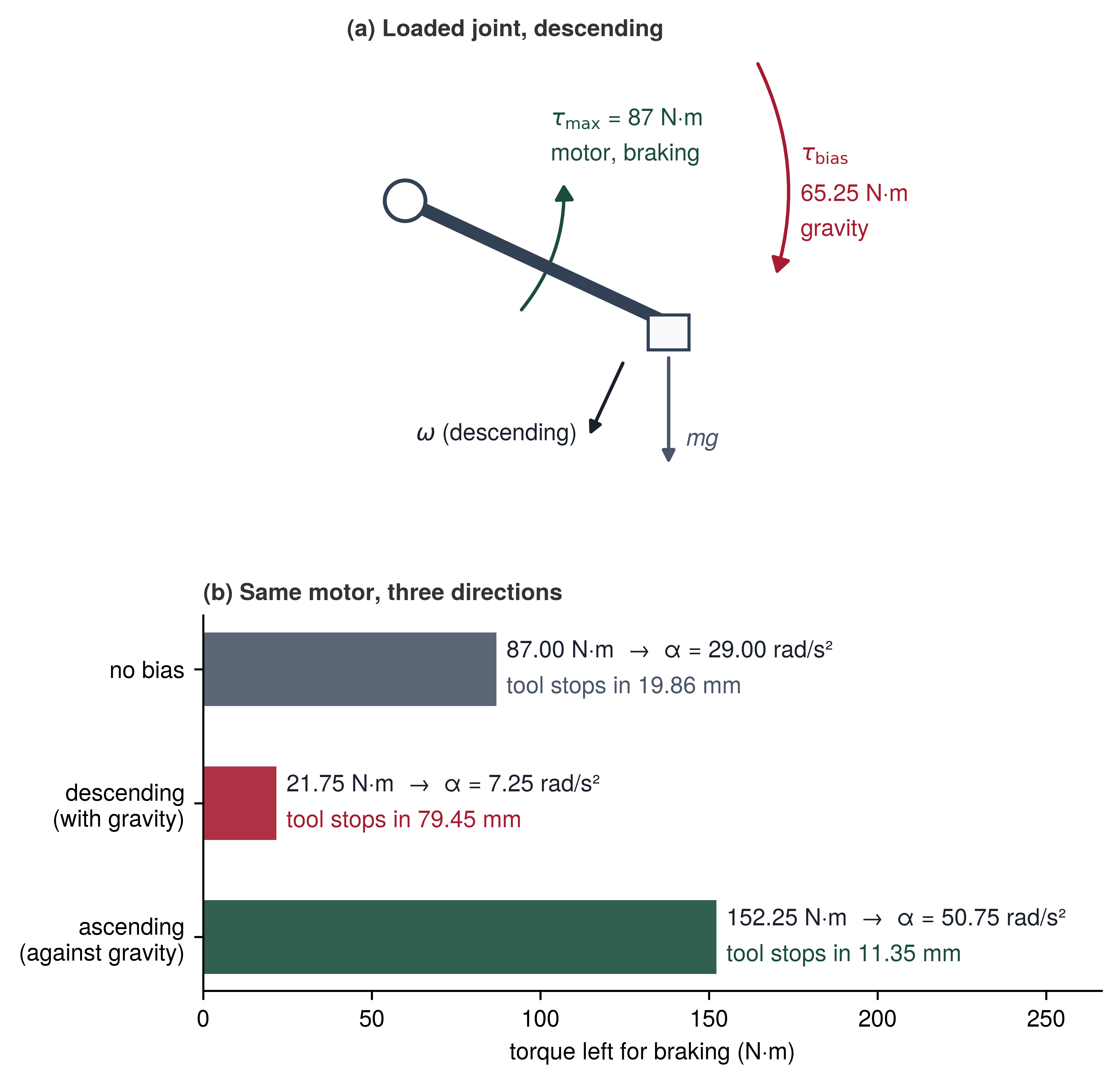
Problem: The loaded joint descends toward the packing station at \(\JointAngularSpeed_0\). How far does the tool point travel before the joint stops when the whole peak torque brakes, and how far when gravity on the arm and mug holds part of it?
Variables:
- \(\JointAngularSpeed_0 =\) 1.2 rad/s and \(\LeverArmLength =\) 0.80 m (Illustrative; the joint speed and effective link lever arm of the scenario, see the Reader Guide).
- \(\EffectiveJointInertia =\) 3 kg·m² (Illustrative; joint inertia with the mug).
- \(\JointTorqueLimit =\) 87 N·m (Datasheet; peak torque of the registered arm’s axes 1 to 4).
- \(\JointBiasTorque =\) 65.25 N·m, 75 percent of peak torque (Illustrative; gravity on the arm and mug in the direction of motion).
Math: With no bias, \(\UnbiasedAngularBrakingDeceleration = \JointTorqueLimit/\EffectiveJointInertia =\) 29 rad/s², the stopping angle is \(\JointAngularSpeed_0^2/(2\UnbiasedAngularBrakingDeceleration) =\) 0.0248 rad (1.42\(^\circ\)), and the tool point travels \(\LeverArmLength\,\FiniteChange\JointAngle =\) 19.86 mm. On the descent, equation 3 leaves \(\JointTorqueLimit - \JointBiasTorque =\) 21.75 N·m for braking, so \(\NetAngularBrakingDeceleration =\) 7.25 rad/s², the stopping angle is 0.0993 rad (5.69\(^\circ\)), and the tool travels 79.45 mm.
Result: The descending stop is four times the unbiased one, an unbudgeted overrun of 59.59 mm for an enforcer that assumes the datasheet torque.
Systems insight: Stopping distance scales as \(1/\NetAngularBrakingDeceleration\), so a bias that takes 75 percent of the torque quadruples the braking term of \(\StoppingDistance\) at the same speed. The certificate must use the net authority in the worst direction, not the actuator’s rating.
The asymmetry is direction, not magnitude (figure 6). On the descent, gravity torque acts with the motion and leaves only 21.75 N·m of the motor’s peak for braking, while the same joint moving up recruits gravity and stops in less distance than the unbiased case. Whether the descending overrun reaches the workstation depends on the clearance left when braking begins, the margin the barrier certificate of section 12.4 evaluates. The coworker’s hand must never fall within the arm’s biased stopping distance of 79.45 mm plus its blind travel during sensing and communication delay before the handover channel engages.
An unprotected integrator downstream of the safety enforcer can introduce severe latency during actuator saturation. If clipping does not halt integration, tracking error continues to accumulate in the controller state. When the safety system subsequently requests maximum braking, the command must pass through this wound-up state rather than bypassing it. The actuator command consequently remains pinned at its forward saturation limit while the integrator unwinds. Take an illustrative case in which tracking error accumulates for 200 ms and the unwinding phase then delays net braking deceleration by \(\IntegratorUnwindDelay =\) 150 ms. The two durations are independent assumptions rather than one derived from the other; the unwind time depends on the integrator gain and on how sharply the error reverses, and only a test of the actual drive fixes it. At an aisle speed of 1.3 m/s, this latency adds \(\SpeedAtDetection\,\IntegratorUnwindDelay =\) 195 mm of unbraked travel. That overrun exceeds the system’s entire 131.0 mm unallocated clearance buffer by 63.99 mm, even before dispatch-to-admission latency is charged. Classical techniques such as integrator clamping, back-calculation, and conditional integration prevent windup in the feedback loop (Åström and Hägglund 2006; Franklin et al. 1998). The enforcement architecture, however, must explicitly quantify any residual unwinding delay and budget the corresponding unbraked distance into the stopping horizon.
Åström, Karl Johan, and Tore Hägglund. 2006. Advanced PID Control. ISA-The Instrumentation, Systems,; Automation Society.
Franklin, Gene F, J David Powell, and Michael L Workman. 1998. Digital Control of Dynamic Systems. 3rd ed. Addison-Wesley.
Actuator saturation is one of the few hardware limitations with an immediate, deterministic detector inside the permission path. On each 1 ms tick, the permission path compares the commanded effort \(\CommandedActuatorEffort\) against the realizable actuator envelope: \(\RealizedActuatorEffort = \text{clip}(\CommandedActuatorEffort, \MinimumActuatorEffort, \MaximumActuatorEffort)\). A nonzero residual \(\CommandedActuatorEffort - \RealizedActuatorEffort \neq 0\) or an active drive-stage current-limit flag directly reveals that the requested effort has been clipped. This comparison detects saturation at the command interface, however, rather than measuring delivered shaft torque or tire-ground traction. Qualified physical evidence (phase currents, DC bus voltage, thermal derating thresholds, and kinematic state telemetry) must support a conservative lower bound on available directional braking deceleration. An upper actuator-effort ceiling limits possible braking; it does not establish the braking that a stop may credit, and a clipping detector does not measure tire-floor traction.
Because degraded authority immediately lengthens stopping distance, the enforcer updates its braking envelope in real time. Before admitting the next trajectory segment, the filter recomputes the effective deceleration \(\NetBrakingDeceleration = (\MaximumActuatorEffort - \lvert \ActuatorBiasEffort\rvert) / \Mass\). Allowable vehicle velocity scales down as authority contracts; if the recalculated stopping distance no longer fits within the confirmed clear distance, the enforcer must command immediate deceleration while sufficient braking headroom remains.
Authority exhaustion must also be communicated upstream to the planner. If a 20 \(\text{Hz}\) trajectory generator continues commanding aggressive accelerations while the low-level 1 kHz loop reports saturation, the policy is planning trajectories for a virtual body that the physical robot cannot realize. The permission path treats saturation as an active constraint violation. It revokes the active trajectory lease and forces a replan initialized from the machine’s actual, authority-constrained dynamic state.
Checkpoint 12.1: Stopping envelope and actuator headroom
Consider how the stopping envelope, and the actuator authority beneath it, bound permissible motion:
12.4 Safe Sets as Conditional Permission
Once gravitational bias torque is counted, the descending arm analyzed in section 12.3 requires 79.45 mm of tool travel to brake to a complete stop, and this stopping distance scales quadratically with approach speed. A clearance margin that guarantees safety at one velocity fails completely at a higher velocity. The runtime safety enforcer therefore requires a joint predicate over position and velocity that it can evaluate synchronously on every tick of the control clock.
While a stopping budget establishes a static physical margin, a control barrier function4 transforms that spatial margin into an instantaneous constraint on the next actuator command (Ames et al. 2014; Ames et al. 2019). This formulation belongs to the broader family of safety filters that monitor candidate action proposals against certified fallbacks, intervening only when necessary (Hsu et al. 2024) so that the machine can execute aggressive tasks while guaranteeing sufficient braking authority to halt.
4 Barrier Function: In constrained optimization, an interior barrier term such as \(-\log(-\InequalityConstraintFunction(\OptimizationIterate))\) grows without bound near constraint boundaries, preventing numerical iterates from escaping the feasible set. Barrier certificates extended this mathematical principle to dynamical systems, proving that no trajectory starting in a safe set can ever reach an unsafe state (Prajna and Jadbabaie 2004). Control barrier functions subsequently formulated this certificate as an explicit, affine condition on the instantaneous control input (Wieland and Allgöwer 2007). While an optimization algorithm’s safety guarantee holds because its numerical iterates are evaluated exactly in software, a physical plant’s safety guarantee holds only as long as actuator limits, dynamics, and real-time execution match the model assumed by the certificate.
Prajna, Stephen, and Ali Jadbabaie. 2004. “Safety Verification of Hybrid Systems Using Barrier Certificates.” Hybrid Systems: Computation and Control (HSCC), Lecture notes in computer science, vol. 2993: 477–92. https://doi.org/10.1007/978-3-540-24743-2_32.
Wieland, Peter, and Frank Allgöwer. 2007. “Constructive Safety Using Control Barrier Functions.” IFAC Proceedings Volumes 40 (12): 462–67. https://doi.org/10.3182/20070822-3-ZA-2920.00076.
5 Nagumo’s Theorem: Nagumo (1942) established that, under conditions ensuring unique solutions, a closed set is forward-invariant if and only if the system vector field points into the set or remains tangent to its boundary at every boundary point; viability theory subsequently formalized and generalized this principle. Because Nagumo’s condition applies to continuous-time flows, a digital controller executing at periodic control ticks requires an inter-sample buffer, sized among the conditions forward invariance rests on (section 12.6.3), to guarantee physical safety between discrete updates.
Nagumo, Mitio. 1942. “Über Die Lage Der Integralkurven Gewöhnlicher Differentialgleichungen.” Proceedings of the Physico-Mathematical Society of Japan, 3rd Series 24: 551–59. https://doi.org/10.11429/ppmsj1919.24.0_551.
A safe set \(\ForwardInvariantSafeSet\) collects all system states for which a scalar certificate \(\BarrierFunction(\MechanicalPlantState)\) remains nonnegative. Its boundary represents zero margin, whereas its interior provides positive margin. For the manipulator arm, both position and velocity must enter this certificate because a physical clearance that safely accommodates a slow approach must reject a high-speed approach at the identical position: \[\ForwardInvariantSafeSet = \{\MechanicalPlantState \in \PlantStateSpace \mid \BarrierFunction(\MechanicalPlantState) \ge 0\}, \quad \SafetyBoundaryManifold = \{\MechanicalPlantState \in \PlantStateSpace \mid \BarrierFunction(\MechanicalPlantState) = 0\}, \quad \text{Int}(\ForwardInvariantSafeSet) = \{\MechanicalPlantState \in \PlantStateSpace \mid \BarrierFunction(\MechanicalPlantState) > 0\}.\] Ensuring that trajectories remain inside \(\ForwardInvariantSafeSet\) is known as forward invariance, the physical counterpart to an inductive loop invariant in formal software verification: \[\BarrierFunction(\MechanicalPlantState_0) \ge 0 \quad \land \quad \BarrierFunctionRate(\MechanicalPlantState, \ControlInput) \ge -\ClassKFunction(\BarrierFunction(\MechanicalPlantState)) \quad \implies \quad \BarrierFunction(\MechanicalPlantState_t) \ge 0 \quad \forall \TimeInstant \ge 0. \tag{4}\] This implication holds in continuous time under valid plant models and actuator feasibility. Nagumo’s theorem5 (Blanchini 1999) provides the geometric boundary interpretation: the closed-loop vector field at the boundary \(\SafetyBoundaryManifold\) must point tangent to or back into the set. The comparison function \(\ClassKFunction(\cdot)\), chosen as an extended class-\(\Glyph{\mathcal{K}}\) function, strictly increases with safety margin and vanishes at zero. This allows rapid approach motions deep inside the interior of \(\ForwardInvariantSafeSet\) while enforcing a nondecreasing safety margin along the perimeter. In an embedded implementation, discrete-time sampling, state estimation noise, and torque delivery latency demand additional safety buffers before continuous-time invariance translates into physical reliability.
Definition 12.2: Control barrier function
A control barrier function is a continuously differentiable scalar function \(\BarrierFunction(\MechanicalPlantState)\) of the plant state whose 0-superlevel set defines the safe set \(\ForwardInvariantSafeSet\), and whose directional derivative can be directly influenced by the control input. Restricting actuation to control inputs that satisfy \(\BarrierFunctionRate(\MechanicalPlantState, \ControlInput) \ge -\ClassKFunction(\BarrierFunction(\MechanicalPlantState))\) guarantees that any trajectory initialized within \(\ForwardInvariantSafeSet\) remains inside \(\ForwardInvariantSafeSet\) for all time (forward invariance, equation 4), provided the plant model, actuator limits, and timing assumptions remain valid.
- Significance: The function translates an empirical stopping margin into an admissible half-space constraint on the next control cycle. For the descending arm of section 12.3, its zero level set sits exactly where remaining tool clearance equals the biased stopping distance of 79.45 mm; closer than this boundary, no admissible torque command can keep the system within \(\ForwardInvariantSafeSet\).
- Distinction: Whereas a Lyapunov function certifies asymptotic convergence toward an equilibrium state, a control barrier function certifies set invariance, proving that system trajectories never exit an admissible operating region. The barrier function provides the mathematical certificate; the least-change quadratic program filter of section 12.6 provides the runtime mechanism to enforce it.
- Common pitfall: Formulating \(\BarrierFunction\) strictly as raw geometric distance. Because distance has relative degree two with respect to torque (commanded torque produces acceleration, which integrates to velocity, which in turn integrates to position), the control input has zero direct authority over \(\BarrierFunctionRate\) at the boundary. A filter monitoring position alone reacts only after physical momentum has made collision unavoidable. An effective barrier must incorporate approach velocity and net braking deceleration, as shown in section 12.4.1.
12.4.1 Kinetic barrier certificates and relative degree
On the descending arm, a barrier function written purely in terms of remaining spatial distance \(\AngularClearance\) leaves commanded motor torque out of its first time derivative, so the safety filter remains blind to closing velocity until the arm reaches the boundary with momentum it can no longer arrest. Across the causal boundary, high-level software proposals meet continuous physical plant dynamics governed by a control-affine differential equation: \[\PlantStateRate = \ControlAffineDriftField(\MechanicalPlantState) + \ControlAffineInputField(\MechanicalPlantState)\ControlInput\] where \(\ControlAffineDriftField(\MechanicalPlantState)\) captures unforced physical drift (including inertia, Coriolis forces, gravitational bias, and passive friction), \(\ControlAffineInputField(\MechanicalPlantState)\) maps control inputs to generalized accelerations, and \(\ControlInput\) represents delivered joint torques. On this robot, embedded motor drives close the internal current and velocity loops, meaning the MCU does not write raw voltages to the coils; the per-tick cycle described in section 12.6.4 converts a torque-space decision into the setpoint and torque limit the drive accepts under the qualified delivered-effort realization contract developed there.
Evaluating how a scalar barrier certificate \(\BarrierFunction(\MechanicalPlantState)\) evolves along state trajectories requires computing its directional time derivative. By the multivariable chain rule, the total time derivative \(\BarrierFunctionRate\) expands across the state velocity \(\PlantStateRate\): \[\BarrierFunctionRate(\MechanicalPlantState, \ControlInput) = \frac{d\BarrierFunction}{d\TimeInstant} = \frac{\partial \BarrierFunction}{\partial \MechanicalPlantState} \PlantStateRate = \nabla \BarrierFunction(\MechanicalPlantState) \cdot \PlantStateRate = \underbrace{\nabla \BarrierFunction(\MechanicalPlantState) \cdot \ControlAffineDriftField(\MechanicalPlantState)}_{\LieDerivativeAlongDrift(\MechanicalPlantState)} + \underbrace{\left(\nabla \BarrierFunction(\MechanicalPlantState) \cdot \ControlAffineInputField(\MechanicalPlantState)\right)}_{\LieDerivativeAlongControl(\MechanicalPlantState)} \ControlInput\] Nonlinear control theory designates \(\LieDerivativeAlongDrift\) and \(\LieDerivativeAlongControl\) as Lie derivatives.6 In modern computational systems, these directional derivatives are standard Jacobian-vector products (JVPs) supported natively by autodiff frameworks such as JAX and PyTorch: \[\LieDerivativeAlongDrift(\MechanicalPlantState) = \nabla \BarrierFunction(\MechanicalPlantState)^\top \ControlAffineDriftField(\MechanicalPlantState) = \text{JVP}(\BarrierFunction, \MechanicalPlantState, \ControlAffineDriftField(\MechanicalPlantState)), \qquad \LieDerivativeAlongControl(\MechanicalPlantState) = \nabla \BarrierFunction(\MechanicalPlantState)^\top \ControlAffineInputField(\MechanicalPlantState) = \text{JVP}(\BarrierFunction, \MechanicalPlantState, \ControlAffineInputField(\MechanicalPlantState)).\] In forward-mode automatic differentiation, a JVP evaluates the derivative along a single tangent vector. When the control matrix \(\ControlAffineInputField(\MechanicalPlantState)\) contains multiple input columns \(\ControlAffineInputField_j(\MechanicalPlantState)\), the notation \(\operatorname{JVP}(\BarrierFunction, \MechanicalPlantState, \ControlAffineInputField)\) denotes the row vector of individual channel products \(\operatorname{JVP}(\BarrierFunction, \MechanicalPlantState, \ControlAffineInputField_j)\). The drift term and the control-channel terms capture distinct physical dynamics:
6 Lie Derivative (the derivative along a flow): Named after Sophus Lie, whose continuous transformation groups generate the flows along which the derivative is taken, the Lie derivative in control theory is identical to the Jacobian-vector product in modern scientific computing. Because both describe the same directional derivative, the automatic differentiation frameworks used during neural policy training can directly evaluate drift and control authority for learned or tabulated barrier functions, whereas the embedded safety enforcer executes the analytical closed form.
- \(\LieDerivativeAlongDrift(\MechanicalPlantState) = \text{JVP}(\BarrierFunction, \MechanicalPlantState, \ControlAffineDriftField(\MechanicalPlantState))\) is the system drift JVP, measuring the rate at which safety margin changes due solely to momentum, gravitational load, and passive dynamics.
- \(\LieDerivativeAlongControl(\MechanicalPlantState) = \text{JVP}(\BarrierFunction, \MechanicalPlantState, \ControlAffineInputField(\MechanicalPlantState))\) is the control authority JVP, measuring the instantaneous sensitivity of the barrier rate of change to commanded actuator torque across the causal boundary.
Formulating an effective barrier certificate requires avoiding the relative degree trap. In computational graph terms, relative degree is the graph distance, counted in time-integrator nodes, between the commanded control input \(\ControlInput\) and the barrier certificate \(\BarrierFunction(\MechanicalPlantState)\). If an engineer defines a safety certificate purely as geometric clearance, \(\BarrierFunction(\MechanicalPlantState) = \ObstaclePosition - \RobotPosition \ge 0\), the commanded actuation is separated from position by two successive integrations: \[\text{Actuation } \ActuatorEffort \xrightarrow{\int \frac{1}{\Mass} d\TimeInstant} \text{Velocity } \RobotApproachVelocity \xrightarrow{\int d\TimeInstant} \text{Position } \RobotPosition\] This two-stage integration cascade establishes relative degree \(\BarrierRelativeDegree = 2\). Taking the first time derivative of clearance yields the closing velocity, \(\BarrierFunctionRate = -\RobotApproachVelocity\), which contains no control input whatsoever (\(\LieDerivativeAlongControl(\MechanicalPlantState) = \text{JVP}(\BarrierFunction, \MechanicalPlantState, \ControlAffineInputField(\MechanicalPlantState)) = \ZeroVector\)). Because the control authority JVP evaluates to zero, motor torque has zero instantaneous authority over the rate of barrier decay. At the boundary of the safe set (\(\BarrierFunction = 0\)), enforcing forward invariance \(\BarrierFunctionRate \ge -\ClassKFunction(0) = 0\) requires \(-\RobotApproachVelocity \ge 0 \implies \RobotApproachVelocity \le 0\). Halting a moving system instantaneously would require infinite deceleration and unbounded torque (\(\ActuatorEffort = -\infty\)). Applying this first-derivative condition to position alone provides no torque constraint before the geometric boundary. Higher-order barrier formulations can retain a position constraint and differentiate until the input appears; this chapter instead incorporates the stopping distance explicitly.
To restore nonzero control authority (\(\LieDerivativeAlongControl \neq \ZeroVector\)), the barrier certificate must explicitly incorporate kinetic energy and braking limits. For an approaching arm joint, let \(\AngularClearance = \ToolClearanceDistance / \LeverArmLength\) represent the remaining angular clearance, \(\JointAngularSpeed > 0\) the approach speed, \(\EffectiveJointInertia \JointAngularAcceleration = \CommandedJointTorque + \JointBiasTorque\) the joint dynamics, and \(\NetAngularBrakingDeceleration\) a validated lower bound on net available angular braking deceleration. Adopting the linear class-\(\Glyph{\mathcal{K}}\) function \(\ClassKFunction(\BarrierFunction) = \LinearBarrierDecayRate \BarrierFunction\), where \(\LinearBarrierDecayRate > 0\) is a constant approach-rate gain, the kinetic barrier certificate is: \[\BarrierFunction(\AngularClearance,\JointAngularSpeed)=\AngularClearance-\frac{\JointAngularSpeed^2}{2\NetAngularBrakingDeceleration}. \tag{5}\] Differentiating \(\BarrierFunction(\AngularClearance,\JointAngularSpeed)\) along the joint dynamics yields \(\BarrierFunctionRate = \LieDerivativeAlongDrift + \LieDerivativeAlongControl\,\CommandedJointTorque\), where \(\LieDerivativeAlongControl = -\frac{\JointAngularSpeed}{\EffectiveJointInertia\NetAngularBrakingDeceleration} \ne 0\) for any nonzero approach speed \(\JointAngularSpeed > 0\). Because commanded torque \(\CommandedJointTorque\) appears directly in this first time derivative with a nonzero coefficient, the kinetic barrier achieves relative degree one (\(\BarrierRelativeDegree = 1\)). Actuator commands now exert immediate control authority across the causal boundary. Enforcing the forward-invariance condition \(\BarrierFunctionRate + \LinearBarrierDecayRate \BarrierFunction \ge 0\) isolates the admissible torque into an explicit affine half-space constraint:7 \[\CommandedJointTorque\le-\JointBiasTorque+\EffectiveJointInertia\NetAngularBrakingDeceleration\left(\frac{\LinearBarrierDecayRate \BarrierFunction}{\JointAngularSpeed}-1\right),\qquad -\JointTorqueLimit\le\CommandedJointTorque\le\JointTorqueLimit. \tag{6}\] In this sign convention, positive angular velocity \(\JointAngularSpeed\), positive gravitational bias \(\JointBiasTorque\), and positive motor torque \(\CommandedJointTorque\) all act downward toward the workstation so that clearance shrinks at rate \(\AngularClearanceRate = -\JointAngularSpeed\), and a negative upper bound on \(\CommandedJointTorque\) in equation 6 therefore sets a minimum magnitude on the upward braking torque \(-\CommandedJointTorque\) that the motor must apply against gravity. This condition defines the linear half-space \(\BarrierConstraintNormal(\MechanicalPlantState)^\top \ControlInput \le \BarrierConstraintBound(\MechanicalPlantState)\) solved by the control barrier function quadratic program (CBF-QP) filter developed next, with the half-space normal and scalar threshold determined directly by the Jacobian-vector products: \(\BarrierConstraintNormal(\MechanicalPlantState)^\top = -\LieDerivativeAlongControl(\MechanicalPlantState)\) and \(\BarrierConstraintBound(\MechanicalPlantState) = \LieDerivativeAlongDrift(\MechanicalPlantState) + \LinearBarrierDecayRate \BarrierFunction(\MechanicalPlantState)\). At standstill (\(\JointAngularSpeed = 0\)), the microcontroller firmware applies a separate static acceleration and position-hold check to prevent division by zero.8
7 Kinetic barrier directional derivative chain rule: Evaluating \(\BarrierFunctionRate(\AngularClearance, \JointAngularSpeed) = \frac{\partial \BarrierFunction}{\partial \AngularClearance}\AngularClearanceRate + \frac{\partial \BarrierFunction}{\partial \JointAngularSpeed}\JointAngularAcceleration\) with \(\AngularClearanceRate = -\JointAngularSpeed\) and \(\JointAngularAcceleration = (\CommandedJointTorque + \JointBiasTorque)/\EffectiveJointInertia\) yields \(\BarrierFunctionRate = (-\JointAngularSpeed - \frac{\JointAngularSpeed\JointBiasTorque}{\EffectiveJointInertia\NetAngularBrakingDeceleration}) - \frac{\JointAngularSpeed}{\EffectiveJointInertia\NetAngularBrakingDeceleration}\CommandedJointTorque = \LieDerivativeAlongDrift(\AngularClearance,\JointAngularSpeed) + \LieDerivativeAlongControl(\AngularClearance,\JointAngularSpeed)\CommandedJointTorque\). Substituting into \(\BarrierFunctionRate + \LinearBarrierDecayRate \BarrierFunction \ge 0\) and rearranging produces \(\frac{\JointAngularSpeed(\CommandedJointTorque + \JointBiasTorque)}{\EffectiveJointInertia\NetAngularBrakingDeceleration} \le \LinearBarrierDecayRate \BarrierFunction - \JointAngularSpeed\). Multiplying by the positive factor \(\frac{\EffectiveJointInertia\NetAngularBrakingDeceleration}{\JointAngularSpeed}\) and subtracting the bias yields equation 6.
8 Standstill velocity thresholding: In microcontroller firmware, floating-point evaluation of \(\frac{\LinearBarrierDecayRate \BarrierFunction}{\JointAngularSpeed}\) is explicitly guarded by a velocity threshold \(\StandstillSpeedThreshold\): when \(|\JointAngularSpeed| \le \StandstillSpeedThreshold\), the kinetic barrier is bypassed in favor of a static acceleration or position-hold bound, preventing floating-point division by zero and NaN exceptions in the sub-millisecond loop.
Applying this kinetic barrier to the descending-arm parameters from section 12.3 sets concrete torque ceilings across the approach. The moment of inertia is \(\EffectiveJointInertia =\) 3 kg·m². The gravitational bias torque is \(\JointBiasTorque =\) 65.25 N·m, directed toward the workstation. The actuator saturation limit is \(|\CommandedJointTorque| \le\) 87 N·m, so the net angular braking deceleration is \(\NetAngularBrakingDeceleration = (\JointTorqueLimit - \JointBiasTorque) / \EffectiveJointInertia =\) 7.25 \(\text{rad/s}^2\). The link lever arm is \(\LeverArmLength =\) 0.80 m, the approach speed is \(\JointAngularSpeed =\) 1.2 \(\text{rad/s}\), and the barrier gain is \(\LinearBarrierDecayRate =\) 10 \(\text{s}^{-1}\). These are stipulated joint-level dynamics that deployment must calibrate on the actual arm. At 110 mm of tool clearance from the workstation surface, the angular clearance is \(\AngularClearance =\) 0.1375 \(\text{rad}\) and the barrier certificate evaluates to \(\BarrierFunction =\) 0.0382 \(\text{rad}\), so substituting into equation 6 requires the joint to deliver at least 80.1 N·m of counteracting braking torque. Most of that demand is not deceleration at all, because the first 65.25 N·m merely cancels gravity to keep the joint from speeding up and only the remainder slows it, which is why a joint still outside its zero set already asks for most of its peak torque. At 79.45 mm, the system reaches the zero set (\(\BarrierFunction = 0\)) where the barrier demands 87 N·m, the motor’s full peak torque capacity. If clearance degrades further to 70 mm, the inequality demands 89.1 N·m, which exceeds peak actuator limits and places the state outside the control-admissible viable set. There, under these scalar dynamics, fixed bias, and instantaneous maximum-braking assumptions, no controller initiated at that point can prevent contact.
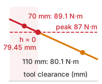
Inside 79.45 mm of clearance the barrier asks for more braking than the joint has.
Physical robotic hardware provides neither perfectly continuous state feedback nor instantaneous torque response. Stator current rise times, fieldbus jitter, and drivetrain mechanical compliance delay and soften corrective torque delivery. To guarantee safety under these real-world non-idealities, the runtime enforcer evaluates the barrier certificate against an inset boundary that explicitly accounts for the worst-case stopping deficit induced by hardware latency and compliant dynamics. This initiates corrective filtering earlier along the trajectory.
This kinetic barrier construction follows directly from rigid-body braking mechanics. For the stipulated scalar approach with exact dynamics, fixed bias, instantaneous effort, and no omitted margins, its zero level set represents the exact boundary of states from which maximum allowable braking stops the joint before collision: the viability kernel (Aubin 1991) of a double integrator subject to actuator saturation. Among collision-free states, the kernel’s complement is the set of inevitable collision states defined in Inevitable collision states. With a conservative available lower bound instead of exact maximum braking, the same construction supplies a sufficient stopping set rather than the exact kernel. The resulting torque requirement remains compatible with the stipulated actuator limits. At \(\BarrierFunction = 0\), the inequality in equation 6 demands exactly \(-\JointTorqueLimit\), and for all \(\BarrierFunction > 0\) the demand is strictly less restrictive, ensuring that at least one admissible control command exists everywhere within the safe set. Actuator feasibility across the entire set, not merely the calculus of the derivative, is what qualifies \(\BarrierFunction(\AngularClearance, \JointAngularSpeed)\) as a valid barrier certificate under input constraints.
This identical principle governs autonomous base navigation. The mobile base certificate \(\MobileBaseBarrierFunction(\ClearDistance, \SpeedAtDetection) = \ClearDistance - [\SpeedAtDetection\,\PrebrakeDelay + \ResidentStopDistance(\SpeedAtDetection) + \LocalizationBound + \ProtectiveClearanceMargin + \TrackingErrorBound]\) is nonnegative precisely when the stopping subtotal in equation 1 fits the clearance. The operational certificate must additionally subtract the dispatch-to-admission travel before granting permission. Both constructions reserve the motion needed to stop. A nonnegative stopping reservation alone does not establish forward invariance; the sampled implementation must also preserve that reservation under its qualified state, effort, and timing bounds. The single-joint arm derivation omits latency and localization margins temporarily only to isolate the mechanics of relative degree.
When complex nonlinear dynamics prevent closed-form analytical solutions for the viability kernel, Hamilton-Jacobi (HJ) reachability9 computes the boundary numerically as the zero level set of an optimal control value function (Mitchell et al. 2005; Bansal et al. 2017). The resulting tabulated lookup surface serves as the runtime barrier certificate, with its spatial gradient defining the half-space normal for real-time filtering. Because state-space grid discretization scales exponentially with dimensionality, HJ reachability lookup tables are best suited for decoupled, low-dimensional subsystems such as a single revolute joint or the longitudinal tracking channel of a mobile base.
9 Hamilton-Jacobi Reachability: Originating in the zero-sum differential game formulations of Isaacs (1965), reachability analysis frames safety as a game between a control policy and a worst-case adversarial disturbance. The resulting safe set contains precisely those states from which the controller can guarantee safety against any bounded disturbance trajectory. Consequently, an HJ reachability table is inherently robust but conservative, and its safety guarantee holds only within the assumed disturbance envelope.
Isaacs, Rufus. 1965. Differential Games: A Mathematical Theory with Applications to Warfare and Pursuit, Control and Optimization. Wiley.
Bansal, Somil, Mo Chen, Sylvia Herbert, and Claire J. Tomlin. 2017. “Hamilton-Jacobi Reachability: A Brief Overview and Recent Advances.” 2017 IEEE 56th Annual Conference on Decision and Control (CDC), 2242–53. https://doi.org/10.1109/CDC.2017.8263977.
↪ The Hamilton-Jacobi value function and its differential-game formulation are developed in Hamilton-Jacobi reachability and worst-case differential games.
A barrier certificate specifies which actuator commands preserve forward invariance, but it does not specify how the runtime safety path should handle an uncertified proposal. When a candidate command violates the half-space constraint, the enforcer must choose whether to project the command onto the boundary of admissible inputs, reject it in favor of a precomputed emergency braking trajectory, or maintain the previously certified setpoint. This intervention policy determines how mathematical barrier constraints translate into real-time authority over the motor drives.
12.6 The Minimal Intervention Principle and Optimization Filters
When the arm approaches the cage-door latch too quickly while still proposing a useful target and direction, rejecting every such proposal would discard useful learned behavior, whereas accepting it unchecked would exceed the permitted approach speed. The minimal intervention principle resolves this trade-off by passing an admissible proposal untouched and choosing the smallest feasible correction, one that satisfies physical constraints and finishes before the permission deadline, whenever a proposal crosses a boundary. The resulting safety shield11 preserves useful task progress within the physical limits. For the torque forbidden by equation 6, the correction should remove only the constraint violation; replacing every near-boundary command with a stop would discard admissible learned behavior.
11 Shielding: In safe reinforcement learning, a shield sits between the learning agent and its environment and overrides only those actions that would violate a temporal-logic safety specification (Alshiekh et al. 2018). The CBF-QP is a continuous-control shield. Its override is the smallest torque change rather than a substituted discrete action, and its specification is a stopping margin rather than a logic formula, which lets it keep the learned action’s direction instead of replacing it.
Alshiekh, Mohammed, Roderick Bloem, Rüdiger Ehlers, Bettina Könighofer, Scott Niekum, and Ufuk Topcu. 2018. “Safe Reinforcement Learning via Shielding.” Proceedings of the AAAI Conference on Artificial Intelligence 32. https://doi.org/10.1609/aaai.v32i1.11797.
Ames, Aaron D., Xiangru Xu, Jessy W. Grizzle, and Paulo Tabuada. 2017. “Control Barrier Function Based Quadratic Programs for Safety Critical Systems.” IEEE Transactions on Automatic Control 62 (8): 3861–76. https://doi.org/10.1109/TAC.2016.2638961.
For the already-derived torque half-space, the enforcer solves a constrained least-change problem, the CBF-QP safety filter (Ames et al. 2017). The tracker supplies the nominal effort; the barrier and actuator limits constrain the result. The combined program of Control Lyapunov functions and stabilization, which optimizes convergence and safety together and relaxes convergence when they conflict, is not needed here. The tracker of The Tracker Handoff and Dynamic Reference Envelopes already supplies the nominal effort, and the filter has only to keep it inside the barrier: \[\min_{\ControlInput \in \mathbb{R}^\ControlInputDimension} \frac{1}{2}\|\ControlInput - \NominalControlCommand\|^2 \quad \text{s.t.} \quad \BarrierConstraintNormal(\MechanicalPlantState)^\top \ControlInput \le \BarrierConstraintBound(\MechanicalPlantState), \quad \ActuatorTorqueLowerBound \le \ControlInput \le \ActuatorTorqueUpperBound \tag{7}\] where the half-space normal and threshold are defined by the directional derivatives \(\BarrierConstraintNormal(\MechanicalPlantState)^\top = -\LieDerivativeAlongControl(\MechanicalPlantState)\) and \(\BarrierConstraintBound(\MechanicalPlantState) = \LieDerivativeAlongDrift(\MechanicalPlantState) + \ClassKFunction(\BarrierFunction(\MechanicalPlantState))\) derived in section 12.4.1, matching the single-axis torque constraint of equation 6, and \([\ActuatorTorqueLowerBound, \ActuatorTorqueUpperBound]\) represents the verified actuator torque envelope. The selected implementation allocates 150 \(\MicroUnitPrefix\text{s}\) to this solve. Dedicated memory and a fixed iteration cap support that target; qualification must establish completion or a timely fallback under the admitted constraint set.
12.6.1 Closed-form quadratic programming and torque projection
Clamping each joint axis independently, or projecting a command onto a barrier and then clipping it to motor torque limits afterward, can leave the coupled stopping constraint violated while skewing the direction of motion across task space. A single active barrier admits a closed-form projection when the projected command also lies inside the actuator bounds; if a bound becomes active, the enforcer must solve for the intersection rather than project onto the barrier and clamp afterward.
For a nonzero constraint normal and inactive actuator bounds, the single barrier constraint \(\BarrierConstraintNormal^\top \ControlInput \le \BarrierConstraintBound\) in equation 7 admits the closed-form projection derived in Minimal-intervention quadratic program: \[\CertifiedControlAction = \NominalControlCommand - \BarrierProjectionMultiplier^* \BarrierConstraintNormal, \qquad \BarrierProjectionMultiplier^* = \max\left(0, \frac{\BarrierConstraintNormal^\top \NominalControlCommand - \BarrierConstraintBound}{\|\BarrierConstraintNormal\|^2}\right) \tag{8}\] where the optimal dual multiplier \(\BarrierProjectionMultiplier^* \ge 0\) is zero whenever the nominal proposal is safe (\(\BarrierConstraintNormal^\top \NominalControlCommand \le \BarrierConstraintBound\)), leaving \(\CertifiedControlAction = \NominalControlCommand\). It is strictly positive when the proposal breaches the boundary (\(\BarrierConstraintNormal^\top \NominalControlCommand > \BarrierConstraintBound\)). In that case it scales the minimal intervention vector \(\FiniteChange \ControlInput = -\BarrierProjectionMultiplier^* \BarrierConstraintNormal\), which projects \(\CertifiedControlAction\) orthogonally onto the safe half-space boundary \(\BarrierConstraintNormal^\top \ControlInput = \BarrierConstraintBound\).
On a two-axis manipulator with illustrative values, suppose the tracker following setpoints from an unconstrained neural policy computes nominal joint torques \(\NominalControlCommand = [\) 3.5, 3 \(]^\top\text{ N}\cdot\text{m}\) against a validated safety half-space \(\BarrierConstraintNormal^\top \ControlInput \le \BarrierConstraintBound\). Its parameters are \(\BarrierConstraintNormal = [\) 2, 1 \(]^\top\) and \(\BarrierConstraintBound =\) 5 \(\text{N}\cdot\text{m}\). The per-joint actuator limits are ±5 \(\text{N}\cdot\text{m}\). Because the candidate gives \(\BarrierConstraintNormal^\top \NominalControlCommand =\) 10 \(\text{N}\cdot\text{m}\) and breaches the boundary by 5 \(\text{N}\cdot\text{m}\), equation 8 yields \(\BarrierProjectionMultiplier^* =\) 1 and projects the command to \(\CertifiedControlAction = [\) 1.5, 2 \(]^\top\text{ N}\cdot\text{m}\). This meets the half-space exactly while keeping both joints within their limits at an intervention norm of 2.236 \(\text{N}\cdot\text{m}\). By contrast, an independent per-axis clamp that ignores the coupling and cuts only the joint with the larger normal component holds Joint 1 to 2 \(\text{N}\cdot\text{m}\) while passing Joint 2 at 3 \(\text{N}\cdot\text{m}\). That clamp gives \(\BarrierConstraintNormal^\top \ClampedControlCommand =\) 7 \(\text{N}\cdot\text{m}\), still 2 \(\text{N}\cdot\text{m}\) outside the constraint, while skewing the torque vector from 40.6\(^\circ\) to 56.3\(^\circ\). The per-axis clamp both violates the coupled constraint and distorts the command. Orthogonal projection satisfies the constraint with the smallest possible torque change, though it too rotates the torque vector, so the resulting end-effector path still requires checking against the coupled plant model.
This geometric behavior exposes the distinction between torque-space and task-space minimal intervention: an orthogonal projection \(\CertifiedControlAction = \NominalControlCommand + \FiniteChange \ControlInput\) minimizes joint effort deviation \(\|\ControlInput - \NominalControlCommand\|^2\), which redistributes multi-axis joint torques and rotates the net Cartesian wrench. While a feasible projection can preserve the safe set \(\ForwardInvariantSafeSet\) under the stated model and timing assumptions, it deflects the end-effector trajectory and may arrest task progress. If the upstream neural policy continues emitting unprojected nominal setpoints without awareness of the intervention, the robot can chatter or stall at the boundary. The downstream enforcer must therefore stream the intervention vector \(\FiniteChange \ControlInput\) back to the application processor as a telemetry signal, notifying the high-level planner to re-plan around the newly active physical constraint.
The same correction has a picture in state space and one in torque space (figure 7). In state space, a trajectory that would breach the velocity-dependent boundary \(\SafetyBoundaryManifold\) is turned along it; in the torque plane, the projection places \(\CertifiedControlAction\) on the half-space boundary \(\BarrierConstraintNormal^\top \ControlInput = \BarrierConstraintBound\), while the per-axis clamp leaves \(\ClampedControlCommand\) outside it and skews its direction.
Filter choice joins a mathematical condition to a measured execution budget and the machine’s available braking authority. As summarized in table 2, architectural choices differ in their handling of relative degree, solver worst-case execution time (WCET), forward invariance guarantees, and directional fidelity. Independent clamping can miss coupled constraints; a CBF-QP can enforce a derived half-space if it is feasible and finishes within the verified cycle. Predictive filters (Wabersich and Zeilinger 2021) trade a longer horizon for configuration-dependent compute cost.
Wabersich, Kim P., and Melanie N. Zeilinger. 2021. “A Predictive Safety Filter for Learning-Based Control of Constrained Nonlinear Dynamical Systems.” Automatica 129: 109647.
Gurriet, Thomas, Mark Mote, Aaron D. Ames, and Eric Feron. 2018. “An Online Approach to Active Set Invariance.” 2018 IEEE Conference on Decision and Control (CDC), 3592–99. https://doi.org/10.1109/CDC.2018.8619139.
Chen, Yuxiao, Mrdjan Jankovic, Mario Santillo, and Aaron D. Ames. 2021. “Backup Control Barrier Functions: Formulation and Comparative Study.” 2021 60th IEEE Conference on Decision and Control (CDC), 6835–41. https://doi.org/10.1109/CDC45484.2021.9683111.
Fisac, Jaime F., Anayo K. Akametalu, Melanie N. Zeilinger, Shahab Kaynama, Jeremy Gillula, and Claire J. Tomlin. 2019. “A General Safety Framework for Learning-Based Control in Uncertain Robotic Systems.” IEEE Transactions on Automatic Control 64 (7): 2737–52. https://doi.org/10.1109/TAC.2018.2876389.
The rows of table 2 belong to one unified family rather than rival techniques (Hsu et al. 2024): each filter monitors a candidate against a fallback policy known to keep the machine safe and intervenes whenever the candidate would leave the set from which that fallback still works, differing only in how the intervention occurs. Whereas a least-restrictive filter passes the proposal untouched up to the boundary and then switches abruptly to the fallback (which is simple to implement but chatters along the boundary), a smooth filter such as the CBF-QP blends in a correction before the boundary is reached. This chapter’s enforcer combines both mechanisms: admitting a trajectory only with a matched stop suffix and holding a state-matched fallback for every reachable state forms a backup-set filter that checks safety by rolling the fallback forward from the proposed state (Gurriet et al. 2018; Chen et al. 2021). The per-tick CBF-QP acts as the smooth local filter layered on top of it, and HJ reachability (Fisac et al. 2019) supplies the value function when a precomputed surface replaces a closed-form barrier.
| Filter | Input and condition | What it can establish | Main validation task |
|---|---|---|---|
| Independent torque clamp | Each axis checked separately | Hardware amplitude limit, not coupled stopping clearance | Test coupled wrench and stopping behavior |
| First-order CBF-QP | Barrier whose first derivative contains the input | Conditional invariance from a viable initial state | Validate model, feasible torque set, and cycle bound |
| Kinetic / higher-order barrier | Position constraint with speed and braking authority included | Conditional stopping margin before geometric contact | Bound bias torque, delay, estimate error, and discretization |
| Energy tank / passivity filter | State \(\EnergyTankLevel\), power balance \(\EnergyTankPower\), force \(\ContactForceLimit\) | Conditional energy bound; force requires a separately qualified channel | Bound force-sensor bias, calibrate virtual damping matrix \(\VirtualDampingMatrix\), and set reserve floor \(\EnergyTankReserve\) |
| HJ value-function filter | Precomputed value function over a gridded state space | Containment for the modeled region | Verify grid coverage, interpolation error, and disturbance bounds |
| Predictive safety filter | Finite-horizon trajectory and terminal set | Recursive feasibility only under terminal and timing assumptions | Bound full solve time and fallback on timeout |
Operating near an active safe-set boundary can produce chattering. If a learned policy repeatedly proposes an unsafe command, sampled enforcement may switch the active constraint across successive 1 ms ticks. Depending on the plant and controller, rapid torque changes can excite a structural mode or increase motor heating and transmission wear. A tested boundary layer or hysteresis can reduce switching, but its added tracking error must fit inside the validated stopping margin.
The intervention vector \(\FiniteChange \ControlInput = \CertifiedControlAction - \NominalControlCommand\) also measures upstream policy health. A rising intervention frequency or magnitude can indicate proposal drift, a changed task, or a changed plant. Normal filtering can also preserve successful whole-machine service while reducing unassisted proposer autonomy; the log must distinguish these outcomes rather than count every correction as a task failure. Summed over an illustrative rolling window of \(\InterventionWindowDuration =\) 500 ms as \(\sum_{k} \|\CertifiedControlAction_k - {\NominalControlCommand}_k\| \FiniteChange \TimeInstant\), the metric lets the permission path flag divergence for logging or operator notification while the per-tick limits still protect the plant.
12.6.2 Intentional contact and in-contact energy barriers
Once the manipulator arm reaches the cage-door strike plate (\(\AngularClearance = 0\)), the spatial kinetic barrier (equation 5) reduces to \(\BarrierFunction(0, \JointAngularSpeed) = -\JointAngularSpeed^2 / (2\NetAngularBrakingDeceleration) \ge 0\), which admits only zero speed (\(\JointAngularSpeed = 0\)) and freezes the gripper before it can depress the latch. A spatial kinetic barrier operates under the premise that the robot’s objective is to avoid collision (\(\AngularClearance > 0\)), whereas manipulation, grasping, and assembly require intentional physical contact (\(\AngularClearance = 0\)). While the spatial barrier can admit arrival at contact with zero approach speed, it does not govern the subsequent force-controlled interaction where geometric separation no longer supplies the relevant margin. Once the warehouse mobile manipulator’s gripper meets the strike plate at the guarded approach, the arm must push against the latch spring, and the margin that matters is the energy and force it delivers there.
Enforcing safety during intentional contact requires transitioning from a spatial clearance barrier to an energetic passivity barrier. When physical clearance is zero (\(\ClearDistance = 0\)), safety cannot mean zero velocity; it means bounding mechanical energy exchange and normal contact force \(\NormalContactForce\). A controller in physical contact interacts with an unmodeled, potentially stiff environment. If tracking errors or neural policy oscillations pump unmeasured energy into the interface, the closed-loop system undergoes contact chattering, limit cycles, or high-force impact spikes that damage both the workpiece and the robot’s transmission.
To bound active energy exchange, the enforcer augments the controller state with an energy tank \(\EnergyTankLevel(\TimeInstant)\)12 (Ferraguti et al. 2013; Hogan 1985) grounded in passivity. A passive system can return no more energy than its initial stored energy plus the energy it absorbs, so a power-preserving interconnection with a passive environment retains a passive energy balance (while a stability claim additionally requires the appropriate dissipation and state-observability conditions). The tank enforces that property by bookkeeping, acting as a software tally of work rather than a physical store of energy. Every joule that virtual damping removes from the arm’s motion is credited to the tank, and the controller may spend actively only what the tank holds, namely its accumulated credits plus a fixed initial reserve. In this contact formulation, \(\ActiveControlTorque\) denotes the active torque component excluding damping, so the total controller torque is \(\ActiveControlTorque-\VirtualDampingMatrix\GeneralizedVelocities\). The damping term can credit the tank only to the extent that the actuator actually realizes the corresponding dissipative work, and using total torque in the debit while also crediting damping would count the same dissipation twice. With those components separated, the modeled balance is: \[\EnergyTankPower = \GeneralizedVelocities^\top \VirtualDampingMatrix\,\GeneralizedVelocities - \ActiveControlTorque^\top \GeneralizedVelocities \tag{9}\] where \(\GeneralizedVelocities^\top \VirtualDampingMatrix\,\GeneralizedVelocities \ge 0\) is the dissipative power credited under qualified torque tracking and \(\ActiveControlTorque^\top \GeneralizedVelocities\) is active mechanical power. Saturation, delay, or tracking error requires conservative bounds on realized work rather than credit for an unrealized damping request. The enforcer then defines the energy-tank barrier certificate of equation 10: \[\EnergyTankBarrierFunction(\MechanicalPlantState, \EnergyTankLevel) = \EnergyTankLevel - \EnergyTankReserve \ge 0 \tag{10}\] where \(\EnergyTankReserve > 0\) is a reserved baseline. Combined with a hard contact-force limit \(\ContactForceBarrierFunction(\MeasuredContactForce) = \ContactForceLimit - \|\MeasuredContactForce\| \ge 0\), the enforcer establishes the in-contact viable set \(\InContactViableSet\). While \(\EnergyTankLevel > \EnergyTankReserve\) and \(\|\MeasuredContactForce\| < \ContactForceLimit\), candidate neural actions are admitted to perform manipulation. If the task consumes the allocated energy budget (\(\EnergyTankLevel \to \EnergyTankReserve\)) or contact force approaches \(\ContactForceLimit\), the barrier filter clamps active energy injection (\(\ActiveControlTorque^\top \GeneralizedVelocities \le 0\)), restricting active work under the modeled power balance. This energy constraint does not by itself bound contact force, because a passive interaction with a stiff surface can still produce a large force. The force channel needs its own sensing-error, response-delay, and actuator bounds before the combined constraints can justify continued contact.
12 Dissipativity: Willems (1972) generalized circuit passivity to any dynamical system with a storage function, an energy-like quantity that can grow no faster than the power supplied to the system. Interconnected passive systems inherit that bound, which is why contact with an unknown but passive environment can be kept stable without a model of the environment. The energy tank is a storage function that the controller keeps explicitly in software, so the bound holds only as far as the tank’s bookkeeping matches the work the actuators actually do.
Willems, Jan C. 1972. “Dissipative Dynamical Systems Part I: General Theory.” Archive for Rational Mechanics and Analysis 45 (5): 321–51. https://doi.org/10.1007/BF00276493.
For a contact command, integrating the work balance in equation 9 over one control interval \(\FiniteChange \TimeInstant\) supplies the energy allowance for the same least-change decision. Suppose the current tank level is \({\EnergyTankLevel}_0\ge \EnergyTankReserve\), a conservative lower bound on damping power actually realized is \(\RealizedDampingPower\), and a bounded contact-direction speed \(\ContactDirectionSpeed>0\) is held over this simplified interval. The spendable work is then \({\EnergyTankLevel}_0-\EnergyTankReserve+\RealizedDampingPower\FiniteChange \TimeInstant\). Because a proposed constant force \(\ProposedContactForce \ge 0\) debits \(\ProposedContactForce \ContactDirectionSpeed \FiniteChange \TimeInstant\), the energy allowance caps force at \(\EnergyLimitedContactForce=({\EnergyTankLevel}_0-\EnergyTankReserve+\RealizedDampingPower\FiniteChange \TimeInstant)/(\ContactDirectionSpeed\FiniteChange \TimeInstant)\). Letting \(\ContactForceCap\) denote the smaller of the deliverable force and the contact-force ceiling after sensing and delay allowances, the admitted command under these stipulated scalar conditions is \(\AdmittedContactForce = \min(\ProposedContactForce, \EnergyLimitedContactForce, \ContactForceCap)\), whose debit leaves \({\EnergyTankLevel}_1={\EnergyTankLevel}_0+\RealizedDampingPower\FiniteChange \TimeInstant-\AdmittedContactForce \ContactDirectionSpeed\FiniteChange \TimeInstant\ge \EnergyTankReserve\) while keeping force below the independent cap. The controller can therefore continue useful contact with a reduced force instead of abandoning the task. At the reserve with no credited damping, however, no positive active work is admitted. Zero speed requires a separate force check rather than division by speed, and delayed or uncertain power requires conservative work bounds over the interval.
The force channel’s own bounds can be computed for the running machine’s two contacts: the cage door, which the arm pushes on purpose, and the coworker’s hand, which it must never press too hard. Each calculation turns a force limit into a speed that the enforcement record carries as a channel ceiling, and each rests on premises that only a measurement can settle. They are derived here, where the channel is enforced; the release decision consumes the results as premises.
↪ Contact force and speed ceilings are enforced as release premises in Physical Criteria for Release.
At the door the quantity that matters is how fast force rises. Against a strike plate of stiffness \(\LatchPlateStiffness\), an arm approaching at \(\LatchApproachSpeed\) raises the contact force at \(d\NormalContactForce/d\TimeInstant = \LatchPlateStiffness\,\LatchApproachSpeed\), which at the guarded 0.03 m/s against the 4.0 × 10⁵ N/m plate is 12 N/ms. The contact tripwire fires at \(\ContactTripwireForce =\) 15 N, but the contact loop needs \(\ContactLoopResponseTime =\) 2 ms for detection, command delivery, and torque rise, and the plate keeps compressing by \(\LatchApproachSpeed \ContactLoopResponseTime\) before deceleration begins. The force at physical braking onset is therefore \[\BrakingOnsetContactForce = \ContactTripwireForce + \LatchPlateStiffness\,\LatchApproachSpeed\,\ContactLoopResponseTime \tag{11}\] which evaluates to 39 N, well inside the 100 N latch limit. The limit still binds the stop that follows, because the plate goes on compressing while the arm sheds its remaining kinetic energy: \[\MaximumPlateIndentation = \frac{\BrakingOnsetContactForce}{\LatchPlateStiffness} + \frac{\LatchApproachSpeed^2}{2\ArmStoppingDeceleration} \le \frac{\LatchForceLimit}{\LatchPlateStiffness} \tag{12}\] Against time since first contact (figure 8), force climbs through the tripwire and across the loop-response window to 39 N at brake onset; the commanded stop then bends the curve over to finish at the 100 N latch limit, while an unbraked run crosses the limit within a few milliseconds. The braking term ignores the plate’s spring work, which would help decelerate the arm, so the bound is conservative. Below the limit the plate can compress only 0.15 mm further, and stopping within that distance requires about 3 m/s², an illustrative stop of about 10 ms.
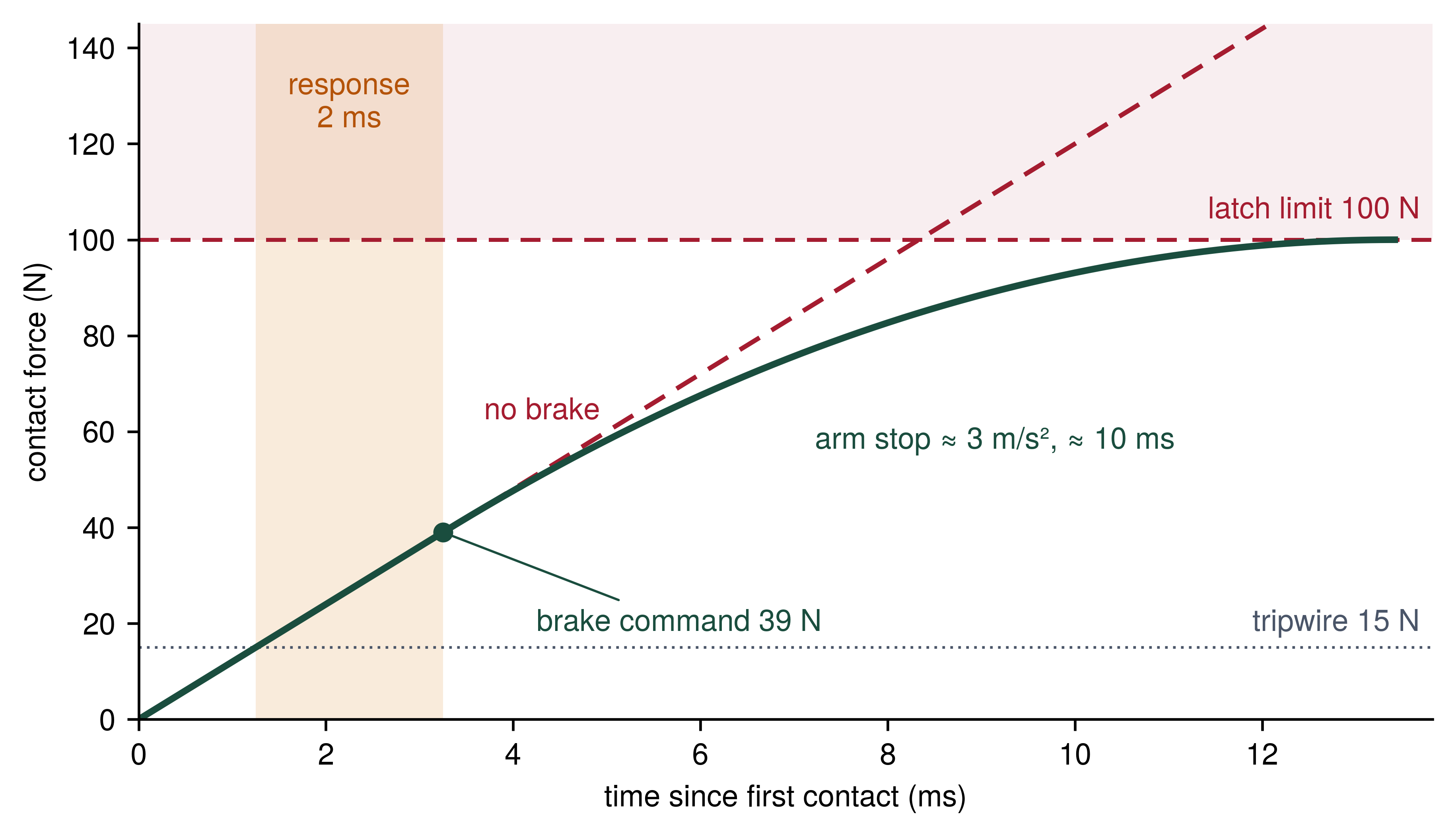
The same two equations show why the approach speed is an enforced channel rather than a preference. At the chunk policy’s proposed 0.10 m/s (section 12.5), equation 11 already gives 95 N at braking onset, and equation 12 then demands an arm deceleration of 400 m/s². The faster approach spends the response interval on force that the stop can no longer absorb. This is the physical half of the refusal in section 12.5; the evidential half is that no trial sampled this speed. Both results treat the arm as rigid and the plate as the whole contact stiffness. Gripper, wrist-sensor, and joint compliance in series lower the effective stiffness and slow the rise, while a geared joint reflects rotor inertia into the moving mass. Whether this arm achieves the required deceleration within a fraction of a millimeter depends on joint torque, drive rise time, and structural stiffness that only arm stopping trials establish. A compliant element placed in series on purpose turns that softening into passive protection. Springs in series add their compliances, so the combined stiffness falls below that of the softer element and the force rises more slowly, a protection that holds even when the enforcer cannot stop in time. The stiffness of that element is therefore part of the contact margin, and Responses when the state remains hidden sizes it for this latch.
The coworker’s hand is the opposite case, a contact the task tolerates only up to a bounded peak force. The force depends first on which contact occurs. In a transient contact the hand is free and recoils, so both bodies move and the collision acts through their reduced mass \(\ReducedImpactMass\). In a clamped (quasi-static) contact the hand is trapped against a rack upright or the robot’s own body, cannot recoil, and receives the full robot-side effective mass at the tool center point, \(\EffectiveImpactMass =\) 12 kg. The biomechanical body model of ISO/TS 15066:2016, whose collaborative-application requirements ISO 10218-2:2025 now incorporates (section 12.8.3), assigns the hand and fingers an effective mass \(\BodyRegionMass\) of 0.6 kg and an effective spring constant \(\HertzianContactStiffness\) of 75 N/mm (International Organization for Standardization 2016, 2025b; Kirschner et al. 2022). This worked example estimates the robot-side mass as half the arm’s moving mass plus its payload capacity; it does not compute the configuration- and direction-dependent mass reflected through the contact Jacobian. In an unbraked elastic contact the peak force is \[\UnbrakedImpactForce = \ContactApproachSpeed\,\sqrt{\HertzianContactStiffness\,\ReducedImpactMass}, \qquad \ReducedImpactMass = \left(\frac{1}{\BodyRegionMass} + \frac{1}{\EffectiveImpactMass}\right)^{-1} \tag{13}\] This is the spring-mass bound of equation 6.7, which equated a moving mass’s kinetic energy to the peak elastic energy of the contact, with one change: two bodies move. Momentum conservation keeps the pair’s common (center-of-mass) motion unchanged through the contact, so only the kinetic energy of their relative motion, \(\frac{1}{2}\ReducedImpactMass \ContactApproachSpeed^2\) for a closing speed \(\ContactApproachSpeed\), can compress the hand, and the reduced mass takes the place of the single moving mass. For this hand and arm, \(\ReducedImpactMass\) is 0.57 kg, because the light hand dominates the sum; a clamped hand is the limit \(\BodyRegionMass \to \infty\), in which \(\ReducedImpactMass\) becomes \(\EffectiveImpactMass\). Solved for speed at a force criterion \(\HandForceCriterion\), the equation gives the channel ceiling \(\ContactApproachSpeed = \HandForceCriterion/\sqrt{\HertzianContactStiffness\,\ReducedImpactMass}\). The peak follows the assumed masses and stiffness; the model establishes neither an impact duration nor a pressure or injury limit.
Kirschner, Robin Jeanne, Nico Mansfeld, Saeed Abdolshah, and Sami Haddadin. 2022. “ISO/TS 15066: How Different Interpretations Affect Risk Assessment.” arXiv Preprint arXiv:2203.02706.
↩︎ The single-mass spring-impact bound that this reduced-mass form extends is established in The sim-to-real contact exploit.
At the arm’s 1 m/s free-space limit even the transient model predicts 207 N, or 4.1× the 50 N criterion, so the arm cannot enter an unseparated contact at that speed. At the handover speed the two contact cases bound the approach very differently (notebook 12.3).
Napkin Math 12.3: The clamped-hand penalty
Problem: The arm approaches the coworker’s hand at the handover speed. What peak force does equation 13 predict for a free hand that recoils and for a hand clamped against a rack upright, and what approach speed does the force criterion allow in each case?
Variables:
- \(\EffectiveImpactMass =\) 12 kg (Derived; the simplified half-arm-mass plus payload-capacity estimate used above).
- \(\BodyRegionMass =\) 0.6 kg and \(\HertzianContactStiffness =\) 75 N/mm (Datasheet; the ISO/TS 15066 hand body model).
- \(\ContactApproachSpeed =\) 0.10 m/s (Chosen; the handover approach while the coworker holds the
accept_itemgrant that Human Authority, Reaction Time, and Clearance defines). - \(\HandForceCriterion =\) 50 N (Chosen; the handover force criterion).
Math: For a free hand, \(\ReducedImpactMass =\) (1/0.6 + 1/12)\(^{-1} =\) 0.571 kg, and with \(\HertzianContactStiffness =\) 75,000 N/m the stiffness term is \(\sqrt{\HertzianContactStiffness\ReducedImpactMass} =\) 207 N per m/s. The peak force is \(\ContactApproachSpeed\sqrt{\HertzianContactStiffness\ReducedImpactMass} =\) 0.10 \(\times\) 207 \(=\) 20.7 N, and the criterion admits \(\HandForceCriterion/\sqrt{\HertzianContactStiffness\ReducedImpactMass} =\) 50 \(/\) 207, or 0.24 m/s. A clamped hand cannot recoil, so \(\ReducedImpactMass\) becomes \(\EffectiveImpactMass\) and \(\sqrt{\HertzianContactStiffness \EffectiveImpactMass} =\) 949 N per m/s. The same approach then delivers 0.10 \(\times\) 949 \(=\) 94.9 N, and the criterion admits only 50 \(/\) 949, or 0.053 m/s.
Result: The free hand sees 20.7 N, inside the criterion; the clamped hand sees 94.9 N, which fails it.
Systems insight: Clamping multiplies the force at any speed by \(\sqrt{\EffectiveImpactMass/\ReducedImpactMass} =\) 4.6, because the whole arm-side mass, not the light hand, sets the collision. A speed ceiling derived for a free hand is therefore a geometric premise as much as a kinematic one.
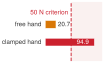
At one handover speed a free hand passes the force criterion and a clamped hand fails it.
The handover channel is therefore a transient-contact ceiling. It holds only while the handover geometry excludes clamping, with the handover point in free space and no rack upright, tote edge, or link of the arm within reach of the hand along the approach. Both contacts end the same way. The arithmetic is exact; what it cannot supply is the premise it rests on, whether an achievable arm deceleration, a contact stiffness, or a clamp-free geometry. The enforcement record keeps each ceiling beside that premise, and the same discipline governs every barrier in this chapter.
12.6.3 The conditions forward invariance rests on
Unmodeled friction loss, actuator saturation, solver overruns, or inter-sample drift under a held torque command can each push a physical plant across a barrier boundary even when the continuous-time inequality is satisfied at the sample instant. The containment claim provided by both spatial and energetic barrier calculations is therefore strictly conditional. A forward-invariance claim requires a feasible barrier and the following bounded conditions; the list is necessary for this design, not an exhaustive if-and-only-if test:
- Model Fidelity: The nominal plant dynamics \(\ControlAffineDriftField(\MechanicalPlantState)\) and \(\ControlAffineInputField(\MechanicalPlantState)\) must capture the true system dynamics within a validated parameter error bound.
- Disturbance Bounds: External forces and unmodeled friction acting on the mass must remain strictly within the modeled disturbance envelope \(|\ExternalDisturbanceForce(\TimeInstant)| \le \DisturbanceForceBound\).
- Actuation Authority: Physical actuators must possess sufficient voltage, current, and thermal headroom to realize the commanded corrective force within a qualified delivered-effort error and response-delay envelope, as well as without saturation (\(\ActuatorEffort^* \in [\MinimumActuatorEffort, \MaximumActuatorEffort]\)).
- Solver Determinism: The optimization solver or projection algorithm must terminate strictly within its allocated execution budget (\(\FilterSolveTime \le \FilterSolveBudget < \PermissionLoopPeriod\)).
- Discretization Invariance: The discrete sampling interval \(\PermissionLoopPeriod\) must be sufficiently small that inter-sample state drift does not breach the continuous-time invariance boundary.
The approach-acceleration upper bound is a separate premise from the lower bound on available braking, and equality of their illustrative magnitudes does not identify their roles. Each of the five conditions maps to a dedicated engineering budget: model fidelity and disturbance bounds come from system identification and bench load testing, actuation authority from dynamometer curves and thermal limits, solver determinism from static worst-case execution time analysis on the MCU, and discretization from the loop period itself. Because the drive holds the last admitted command between samples (a zero-order hold13), the plant drifts for one full period before the next check can act on it. The drift covers at most \(\FiniteChange \ZohHoldTravel = \BodySpeed \PermissionLoopPeriod + \frac{1}{2} \ProfileAccelerationBound \PermissionLoopPeriod^2\) at speed \(\BodySpeed\), where the worst case is the highest speed the base can reach rather than the ceiling \(\SpeedBound\) that admission enforces. At the 1.5 m/s drive limit, an independently stipulated 2 m/s² upper bound on approach acceleration, and \(\PermissionLoopPeriod =\) 1 ms, that drift is 1.501 mm, a small fraction of \(\ProtectiveClearanceMargin\). Tightening a raw-clearance check by this displacement preserves geometric separation over the hold interval under the stated motion bounds, whereas a kinetic or energy barrier requires a bound on its own evolution throughout the interval.
13 Zero-Order Hold: The order counts the derivatives the hold carries forward. A zero-order hold keeps the command’s value constant until the next sample, while a first-order hold would also extrapolate its slope. For one control tick the plant therefore integrates a torque the controller can no longer change, which is the source of the drift buffer \(\BodySpeed \PermissionLoopPeriod + \frac{1}{2}\ProfileAccelerationBound \PermissionLoopPeriod^2\); Discrete-time sampling and zero-order hold phase lag develops the hold’s delay.
A condition that no detector watches is an assumption, so the permission path attaches one to each. A disturbance observer compares predicted with measured acceleration on every cycle. Inverter status registers and current shunts report actuator saturation. A hardware watchdog and cycle counter time the solver against its deadline. Timestamp counters on the sensor bus catch jitter and missed samples. When a detector invalidates a premise, the enforcer cannot restore permission by substituting optimistic parameters. It selects a response whose sensing, effort, and clearance premises survive, as developed in section 12.8. Both the free-space projection and contact decision must finish before the physical margin reserved for computation is spent.
12.6.4 Execution timing in the sub-millisecond loop
A correct barrier calculation delivered after the permission deadline cannot protect the margin reserved for that deadline. The whole cycle must therefore have a bounded execution time (Wilhelm et al. 2008), including state acquisition and the final drive transfer. A real-time operating system can reduce scheduling delays, but its name does not establish a bound on shared-memory or peripheral interference. The permission path’s implementation must be qualified under the competing workloads that can delay it, so the declared cycle allocation below is a timing requirement carried into loaded placement tests rather than a measured trace or a platform-independent solver guarantee.
In this heterogeneous design, the shield executes inside a 1 kHz timer interrupt routine on the MCU. An unloaded cycle of acquisition, validation, and a typical active-set solve completes in about 135 \(\MicroUnitPrefix\text{s}\), an illustrative estimate rather than a bound. The candidate path instead declares a worst-case execution-time requirement of 250 \(\MicroUnitPrefix\text{s}\) for the whole cycle, divided among the stages below, and the whole sequence must finish inside the 400 \(\MicroUnitPrefix\text{s}\) deadline:
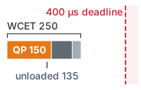
The QP solve takes 150 of the 250 \(\MicroUnitPrefix\text{s}\) declared cycle, inside a 400 \(\MicroUnitPrefix\text{s}\) deadline.
- Interrupt Entry & State Acquisition (30 \(\MicroUnitPrefix\text{s}\)): The hardware timer triggers the interrupt service routine (ISR), and firmware latches the wheel and joint encoder registers and the latest inertial measurement unit (IMU) sample.
- Proposal & Lease Verification (15 \(\MicroUnitPrefix\text{s}\)): The MCU makes one bounded read of its local mailbox, which the link receiver fills outside this routine, validates the checksum, and confirms sequence order before checking evidence age, the active chunk lease, and the host heartbeat timer. In the evidence-age check, the evidence’s age at dispatch is the difference between the source frame’s evidence timestamp and the host dispatch timestamp in the proposal header (Supervisory timers and proposal wire contracts). That age may not exceed 51.8 ms, which combines the 51.6 ms observation age charged in row 5 of table 1 with 0.2 ms of clock uncertainty (The Observation Contract). Passing that test qualifies the evidence only at dispatch, so the MCU also reconstructs the evidence’s current age from its source epoch and elapsed time and checks it against the evidence’s own validity deadline and the remaining physical margin. Inference, admission, waiting, and transfer after dispatch must already be reserved once in that margin through the dispatch-to-admission allocation inside the timing allowance. Otherwise fresh evidence is required before activation, because a new proposal timestamp cannot renew old evidence. The MCU then verifies that elapsed time since valid admission or renewal has not exceeded the 60 ms active chunk lease and reads the host heartbeat timer, which marks the host silent once no heartbeat has arrived within the 30 ms timeout.
- Tracking Contract Verification (10 \(\MicroUnitPrefix\text{s}\)): Firmware evaluates instantaneous tracking error norm \(\|\TrackingErrorDistance(\TimeInstant)\| = \|\CartesianPosition(\TimeInstant) - \ReferencePosition(\TimeInstant)\|\) against the qualified bound \(\TrackingErrorBound\).
- CBF-QP Safety Shield Solve (150 \(\MicroUnitPrefix\text{s}\)): An active-set QP solver14 running in pre-allocated static SRAM, the MCU’s tightly coupled data memory, evaluates active barrier inequalities and computes \(\CertifiedControlAction = \arg\min_{\ControlInput \in \mathbb{R}^\ControlInputDimension} \frac{1}{2}\|\ControlInput - \NominalControlCommand\|^2\). A fixed iteration cap limits the work count; meeting the allocation also requires bounded per-iteration arithmetic, memory access, interrupt interference, and output service, including ill-conditioned constraint geometry. Dynamic memory allocation is forbidden on this path so that heap service is excluded from that timing obligation. In this two-processor design no memory is shared with the host, so camera direct memory access (DMA) streams cannot reach the memory this cycle uses. The couplings that remain are the link receiver, whose DMA writes into the MCU’s own memory, and any shared supply rail or clock; The Placement Record measures that residual interference and tests whether the isolation holds under load.
- Output Selection & Admitted Command Staging (15 \(\MicroUnitPrefix\text{s}\)): If the QP is feasible and constraints hold, the enforcer emits the admitted command. The drives close the velocity and current loops. Because industrial servo drives running in position mode choose torque direction internally from position tracking error while an unsigned torque limit clips only the magnitude of each joint’s effort symmetrically, a position setpoint plus an unsigned torque limit does not by itself realize the signed braking effort or coupled multi-axis half-space the QP requires. This interface needs a qualified mapping from the staged command to delivered effort, with bounded realization error and response delay. The filter tightens each commanded half-space by the largest possible projection of that effort error along its normal, so every effort the drive may realize still satisfies the delivered-effort constraint. Near full braking, that allowance may remove feasibility and require earlier intervention. The drive configuration and qualification evidence must establish these bounds; this example supplies no measured error or delay. During the response interval, a previously held command must remain valid and the intersample/response allowance must cover its effect, charging each delay once. If the position/limit interface cannot satisfy this contract, the design needs a qualified effort interface or a stricter qualified operating envelope and fallback. The next position setpoint and per-axis torque limit travel in the next EtherCAT frame only under that realization contract. Drive-reported torque on the following tick can detect a breach but cannot retroactively certify the preceding interval; an invalid replacement leaves previously admitted setpoints in force only while their own evidence, lease, state, and stopping reservation remain valid.
- Completion & Reserve (30 \(\MicroUnitPrefix\text{s}\)): The MCU checks the register write and services its own watchdog only after the cycle succeeds. The reserve absorbs variation in the stages above; a cycle that has not completed by the deadline requires a qualified preempting timer or an independent mechanism to select the resident fallback before the next tick. The overrunning ISR cannot be assumed to detect and recover from its own stall. Only with that bounded transfer does a missed tick cost the base 1.3 mm of travel at the aisle speed. Empirical Verification of Silicon Isolation tests whether the declared WCET holds under load, so that ticks are not missed.
14 Active-Set QP: An active-set solver guesses which constraints hold with equality, solves the resulting linear system, and adds or drops one constraint per iteration. Dual variants such as that of Goldfarb and Idnani (1983) start from the unconstrained optimum, here the nominal command itself, and add only violated constraints, so a proposal that already satisfies every barrier costs almost nothing. The iteration count is bounded by the combinations of the constraint set rather than by a clock, so a fixed iteration cap bounds steps while the time per step must still be measured under interference.
Goldfarb, Donald, and Ashok Idnani. 1983. “A Numerically Stable Dual Method for Solving Strictly Convex Quadratic Programs.” Mathematical Programming 27 (1): 1–33. https://doi.org/10.1007/BF02591962.
↪ The schedulability analysis that a declared WCET and deadline feed is developed in Real-Time Timers, Watchdogs, and Schedulability.
Stage 5 is also where refusal takes effect. Any of several conditions triggers it. The chunk lease may have expired, the host heartbeat may have fallen silent, the shared drive bus may report undervoltage, tracking error \(\|\TrackingErrorDistance(\TimeInstant)\|\) may exceed \(\TrackingErrorBound\), actuator saturation may render the feasible control set empty (\(\SafeControlSet = \emptyset\)), or an operating-contract detector such as the disturbance observer or the solver deadline may trip. In any of these cases, the output selector withholds the admitted command, revokes policy authority, and selects the state-matched stop. At standstill, lease or heartbeat expiry selects HOLD, the powered standstill hold that section 12.8 defines, only while powered support remains available. Undervoltage instead requires a qualified transition to mechanical restraint before that support expires. In motion, STOP under undervoltage remains conditional on drive survival.
Checkpoint 12.2: Barrier, projection, and cycle budget
The barrier fixes which commands preserve the stop; the filter and its cycle decide whether the chosen command arrives in time.
Every stage of this cycle assumes that the solve returns a feasible command. When saturation empties the admissible torque set, the lease lapses, or the cycle overruns its deadline, projection has nothing to return, and the permission path must already hold a response it can execute without the proposer. Executing that check deterministically while surviving proposer faults requires placing the enforcer where the host processor cannot preempt or bypass it.
12.7 Admission, Cyclic Checking, and Monitor Independence
A planned waypoint can clear a warehouse rack upright in the planner’s geometric check while the physical manipulator overshoots into the steel during execution, and an instantaneous motor torque well within electrical limits can accelerate the arm past the point where its remaining stopping reservation can arrest motion. Relying on trajectory admission alone misses in-flight tracking overshoot and saturation, whereas checking only single-step torque commands without a verified stopping continuation lets the arm enter an inevitable collision state before the local filter reacts. Robust safety enforcement therefore demands both layers (the per-tick cycle of section 12.6.4 on a dedicated MCU and full-plan admission before motion begins). That raises three structural questions: why neither layer can replace the other, where the cyclic checker sits relative to the command stream, and how independent of the proposer the MCU must actually be.
Full-plan admission judges the candidate trajectory, its seams, its swept clearance, and its verified stopping continuation before the machine commits to motion. The expensive geometry behind that judgment (queries of global occupancy octrees, signed distance fields, or mesh collision models) cannot run inside a 1 ms control interrupt merely because the MCU owns final actuation privilege. It therefore runs on the host as a separately scheduled, bounded job, and its result reaches the MCU as the trajectory record. The MCU’s own admission check then verifies that record against bounded, qualified local evidence (the resident stop suffix, its entry state, and the commitment deadline) without traversing the global map. The hard real-time cyclic path evaluates current joint state, remaining lease validity, and available actuator effort on every tick before selecting and dispatching the next physical command.
An in-line checker places its worst-case execution time directly inside the control-loop deadline, consuming a portion of the available compute tick. A parallel monitor instead operates asynchronously alongside the proposal pipeline, avoiding added forward latency during nominal execution but contributing detection latency and trip delay to the physical response budget. Either architectural placement must ensure privilege isolation. The untrusted proposer must never be able to bypass the selected output, and the system must preserve the dedicated sensing and actuation channels required by the fallback controller. As Two Paths and the Resources They Share will show from the resources each candidate placement shares, isolating these execution domains across memory spaces or heterogeneous processing cores is what allows the safety monitor and its fallback mechanisms to survive the very proposer faults that trigger an intervention. The physical stopping budget supplies the non-negotiable temporal and spatial boundaries that this hardware split must satisfy.
Systems Perspective 12.3: The monitor independence rule
Any valid safety claim must explicitly define which proposer failure modes its sensing, compute, and actuation pathways survive. Placing a monitor on a separate physical core or processor does not establish true independence if that monitor shares a power rail, a memory bus, a sensor link, or an unisolated clock domain with the untrusted proposer. Shared hardware resources require provably bounded interference or a qualified, survivable fallback state. Any environmental condition that the monitor cannot observe directly must remain an explicit, documented operating premise rather than an unstated assumption.
The running example assumes qualified drive, scanner, and arm safety functions and a rated lease/heartbeat watchdog; the release case must name the scoped evidence supporting those functions. Independence, however, is not certification. The runtime permission path is not the machine’s certified functional safety layer, and beneath it sit the certified safety functions embedded within motor drives, safety laser scanners, and the dedicated safety controller. These hardware-interlocked mechanisms carry the formal integrity claims that certification bodies audit against industrial standards. The primary operational duty of the software permission path is to regulate the learned proposer proactively so that the robot never trips those certified hardware interlocks during normal operation. Section 12.8.3 maps each dynamic response developed throughout this chapter onto that underlying certified safety floor once the complete response hierarchy is established, and names the one narrow MCU function that does carry a rating.
12.7.1 Where the thesis bends
When a learned locomotion or manipulation policy emits raw joint targets or motor torques at the control rate instead of handing the permission path a multi-step trajectory, the enforcer loses the ability to verify a collision-free stopping continuation before motion begins. It must then either run an active fallback model on every tick or watch its projections induce distributional shift and boundary chattering. Admission and the cyclic check in this chapter both assume that the proposer hands the permission path a plan it can judge before motion: kinematic intent lives in the learned policy, and deterministic motor drives close the torque loops. Much of contemporary robot learning practice abandons this classical division, outputting joint targets at the control rate above stiff proportional-derivative loops (Lee et al. 2020) or emitting motor torques end-to-end. The third law, proposal is not permission (principle 3), does not disappear in such direct control designs. Instead, the range of physical guarantees that the runtime permission path can uphold narrows in precise, quantifiable ways.
Lee, Joonho, Jemin Hwangbo, Lorenz Wellhausen, Vladlen Koltun, and Marco Hutter. 2020. “Learning Quadrupedal Locomotion over Challenging Terrain.” Science Robotics 5 (47): eabc5986.
Four guarantees survive because each acts directly on raw commands at the causal boundary, without requiring a forward plan. A per-tick limit on rate and amplitude bounds torque slew and joint velocity at the hardware register interface. The kinetic barrier of equation 6 operates directly in effort space, so a CBF-QP can filter the policy’s output without converting it to an intermediate kinematic setpoint. The passivity-based energy tank of section 12.6.2 monitors power exchange and bounds the physical work the policy can inject into the environment during contact. Beneath all of these, low-level geofencing, safely-limited speed monitoring, and torque removal backed by mechanical spring brakes remain permanently active under the software stack. Communication timing improves along one dimension. If a qualified freshness deadline is selected at one tick and an independent watchdog enforces it, policy silence is detected within that tick plus bus transport delay, which reduces the lease-expiration travel row of table 1 from 80.6 mm to 2.6 mm at the aisle speed.
What is lost is admission. Without an explicit multi-step trajectory, the system cannot verify the collision-free stopping suffix before the robot commits to motion. The enforcer must instead evaluate the machine’s dynamic stopping reservation on every tick against an active fallback controller that maintains its own internal braking model. On a wheeled mobile base, that fallback is straightforward to formulate. The controller executes a qualified service-braking response along the current heading, followed by wheel restraint after confirmed standstill. On an underactuated balancing machine, such as a bipedal humanoid, the fallback is itself an active balance controller; cutting motor torque produces an immediate uncontrolled fall rather than a safe state.
Runtime projection also alters the closed sensorimotor loop under which the policy was trained. Every time the enforcer projects a proposed action onto the admissible set, it delivers a state to the environment that the policy never intended, precipitating distributional shift in subsequent observations. This penalty surfaces directly in task performance, as quantified by the intervention metrics of section 12.6. Frequent overrides cause the machine to chatter erratically along safety boundaries or freeze conservatively short of its goal. To reconcile this tension, modern architectures adopt filter-aware policy training, incorporating the safety filter directly into the training objective so that the neural network learns to avoid the boundary rather than encountering the enforcer for the first time on physical hardware (Hsu et al. 2024). The core thesis still holds at the causal boundary, where untrusted proposals never bypass runtime enforcement. What bends is how much of the safety argument can be settled mathematically before motion begins vs. how much performance the machine must sacrifice to settle the remainder while moving.
12.8 The Fallback Ladder
A safety filter must select its fallback before the admissible control set becomes empty. Once the chosen filter has an empty feasible intersection, it cannot maintain its modeled invariant. A qualified alternate response may mitigate damage or support its own narrower containment claim, but selecting it does not restore the lost guarantee. Furthermore, physical systems cannot rely on a single, binary kill switch. Abruptly severing DC bus power whenever a control proposal approaches a barrier boundary induces uncontrolled deceleration, mechanical shock, and incessant false-positive mission aborts. Conversely, complex software optimization is futile during a hardware fault such as an inverter shoot-through, because the fault destroys gate-driver field-effect transistors (FETs) milliseconds before an interrupt handler can even dispatch.
To resolve these competing physical realities, the permission path maintains a deterministic ladder of resident protective responses. The runtime arbiter evaluates plant kinematics, remaining sensor validity, and hardware integrity on every control cycle, selecting deterministically among minimally invasive projection, closed-loop position holding, controlled deceleration, or complete torque removal. The name records an ordering by how much control authority each response retains, from a corrected proposal down to unpowered restraint, not a sequence to descend. The arbiter never climbs down the rungs one at a time; it jumps directly to the one whose prerequisites still hold.
Definition 12.3: Dynamic fallback ladder
Dynamic fallback ladder is the set of resident protective responses (\(\ControlInput \in \{\SafeSetProjection(\NominalControlCommand), \PoweredHoldCommand, \ControlledStopCommand, \TorqueCutoffCommand\}\)). A deterministic arbiter selects one of them on every tick according to the check that failed (an invariant violation, a timing overrun, or a hardware fault) and the measured state of the plant. One trigger can therefore select different rungs in motion and at standstill.
- Significance: Physical AI systems cannot treat all faults identically. Cutting actuator power on dynamic, underactuated, or high-momentum plants (for example, legged robots mid-stride or multirotors in flight) precipitates immediate catastrophic falls or tumbling. These platforms require state-matched active deceleration before executing terminal torque removal.
- Distinction: Unlike software exception handlers that unwind the call stack or terminate a user-space thread, a dynamic fallback ladder operates against physical momentum. The arbiter matches each rung to the remaining valid sensor channels, surviving control authority, and available stopping clearance.
- Common pitfall: Treating the rungs as an escalation sequence where lower rungs, such as safe torque off (STO), inherently provide faster or safer arrest. Each rung possesses distinct entry prerequisites; invoking an unpowered torque inhibit on an airborne drone or an unbraked mobile base allows the machine to coast freely without arresting motion.
12.8.1 The four rungs of the fallback ladder
Walking down protective responses one step at a time like a software exception cascade fails on physical hardware: commanding a standstill position hold while the base is rolling at 1.3 m/s saturates the drives, while cutting drive torque before active braking completes lets the vehicle coast into the obstacle. The dynamic fallback architecture therefore organizes protection across four resident responses (PROJECT, HOLD, STOP, and INHIBIT). The deterministic arbiter samples measured plant state (velocity, position, payload loading) and fault severity on every millisecond tick to dispatch the response whose compute, sensing, and actuation prerequisites still hold:
PROJECT, minimal-intervention projection in MCU firmware. The primary safety filter executes on every control cycle while the feasible control set is nonempty (\(\SafeControlSet \neq \emptyset\)), the proposal lease is fresh, and tracking error remains within bounds (\(\|\TrackingErrorDistance(\TimeInstant)\| \le \TrackingErrorBound\)). It computes the minimal-intervention torque \(\CertifiedControlAction = \arg\min_{\ControlInput} \|\ControlInput - \NominalControlCommand\|^2\) subject to active barrier half-spaces within its 150 \(\MicroUnitPrefix\text{s}\) cycle allocation. It makes the smallest feasible effort correction under the stated invariance assumptions; the planner must still account for any changed task-space path.HOLD, powered hold at standstill in MCU firmware. When the machine is stationary, the arbiter selects an energized position hold, analogous to an IEC 60204-1 Category 2 stop: safe stop 2 (SS2) followed by safe operating stop (SOS), the drive function that monitors standstill.15 Its protective validity stems from that certified standstill monitor rather than the position loop gain. Because IEC 60204-1 permits only Category 0 or Category 1 for an emergency stop, HOLD can never serve as an E-stop response (International Electrotechnical Commission 2016a). The drives maintain coordinate \(\PoweredHoldState\) under closed-loop position control, modulating inverter phase currents against gravity and static loads. While this rung incurs continuous Joule heating in motor windings, it eliminates friction brake wear and preserves kinematic calibration, enabling instantaneous task resumption when a valid trajectory proposal arrives. On the warehouse mobile manipulator, this rung handles lapsed leases or lost host heartbeats specifically when the platform is already at standstill.STOP, controlled dynamic stop in MCU firmware. When a machine in active transit loses proposal authority, tracking error diverges, or an obstacle breaches the stopping envelope, the response is a resident, state-matched controlled stop, analogous to an IEC 60204-1 Category 1 stop (safe stop 1, SS1). Its certified counterpart is the ramp-monitored variant (SS1-r), which checks deceleration against a bounded profile throughout the arrest; the unmonitored, time-controlled variant (SS1-t) merely removes torque after a fixed delay without verifying that the planned ramp actually decelerated the load (International Electrotechnical Commission 2016b). The resident jerk-limited S-curve stop suffix of section 12.2 serves this role provided the entry state falls within its validated domain. Executed autonomously by bare-metal MCU firmware directly from local SRAM, this stop peaks at the credible deceleration \(\CredibleBrakingDeceleration\), returning kinetic energy through motor inverters to the DC bus for absorption by the qualified regeneration path. Power removal and mechanical brake clamping occur only after confirmed zero velocity.INHIBIT, torque inhibit and spring-brake clamping by hardware interlocks. When the safety microcontroller suffers a brownout, clock loss, or watchdog timeout, all software decision logic ceases. Dedicated, out-of-band hardware interlocks trigger STO to de-energize gate drive power supplies and drop hold current to electromechanical spring-applied brakes. This terminal rung removes motor torque without software intervention; the mechanical brakes provide only their independently qualified holding or dynamic stopping capacity.
15 Machine Stop Categories: IEC 60204-1 distinguishes uncontrolled power removal (Category 0), controlled stopping followed by power removal (Category 1), and controlled stopping with power retained (Category 2). A category defines electrical power status rather than stopping distance; every rung therefore requires its own empirically validated stopping measurement.
International Electrotechnical Commission. 2016a. IEC 60204-1:2016: Safety of Machinery, Electrical Equipment of Machines, Part 1: General Requirements. International Electrotechnical Commission.
When a machine in motion loses proposal authority or violates a tracking bound, the arbiter engages a controlled dynamic stop, operating analogously to an IEC 60204-1 Category 1 stop. On the warehouse mobile manipulator base, this rung executes the resident stop suffix pre-admitted alongside the motion trajectory, rather than attempting to synthesize a stopping trajectory on the fly during a fault. In steady-state cruising with zero acceleration, this pre-computed profile matches the operating state at fault onset directly; nonzero acceleration states require their own qualified state-matched suffixes. From an aisle cruise velocity of 1.3 m/s, the jerk-limited S-curve suffix sustains a credible peak deceleration of 2 m/s² between its jerk transitions. The entire maneuver spans 931.25 ms and traverses 605.31 mm, the stop-suffix travel the stopping budget of section 12.2 reserves at this speed. Because the deceleration phase channels kinetic energy back through the inverter into the DC bus, bus capacitance and braking choppers must absorb this regenerative surge without triggering a bus overvoltage fault. Complete electrical power removal, if mandated by protocol, occurs only after sensors verify standstill.
Beyond firmware-driven stops, a separate out-of-band circuit can inhibit motor torque generation entirely. Drive STO cuts gate-drive bias to isolate inverter FETs, but it does not disconnect the DC bus, energize mechanical friction brakes, or actively decelerate a moving rotor; an unbraked motor will simply coast under its existing momentum. In robust architectures, an external safety controller simultaneously drives a separately rated contactor and spring-applied mechanical brakes. Engineers must evaluate the dynamic stopping distance of this combined pathway as an integrated system, because dropping drive torque while an arm is under gravitational load or while a vehicle is at speed can exacerbate the hazard. For the warehouse mobile manipulator, this pathway, STO combined with nine spring brakes that engage between 30 ms and 80 ms after coil flux decay, constitutes the unbudgeted INHIBIT rung. It serves exclusively as a hardware backstop for MCU cycle failure, and the primary stopping envelope claims do not rely on it.
An undervoltage fault on the shared drive bus can invoke the STOP rung only while inverter gate drives, angular encoders, and control logic retain adequate voltage for closed-loop deceleration. The isolated permission rail maintains power to logic circuits, transceivers, and brake coils for 2 s, but it does not supply the motor currents required for braking torque. Consequently, timing guarantees for powered stopping assume a surviving drive bus. Under this condition, dynamic braking begins within 22 ms of the fault flag; the hold-up hypothetical uses the pre-dispatch inspected-floor ceiling of 1.23 m/s, rather than an admitted operating configuration, and its stop requires 1211.4 ms. Mechanical brake engagement at standstill adds at most 80 ms. This entire sequence completes within 1313.43 ms, preserving a 686.57 ms buffer of control logic hold-up.
↩︎ The isolated permission rail and its capacitive hold-up are established in Cross-budget coupling and permission rail isolation.
This analysis confirms the control-supply duration budget, whereas the electrical drive-energy budget requires separate qualification. Systems engineers must prove through empirical testing that the DC bus capacitance, inverter power stages, and regenerative dump resistors sustain controlled deceleration under worst-case electrical fault conditions. If the drive stage cannot guarantee this power integrity, the system must either adopt an unpowered dynamic braking configuration or restrict its operational safety envelope; INHIBIT cannot be credited with standard Category 1 stopping performance. Similarly, at standstill, an undervoltage fault must trigger verified mechanical brake engagement before the logic supply decays, rather than attempting to maintain an active HOLD indefinitely on finite capacitance.
Physical AI systems engineers must distinguish between fail-safe and fail-operational plants when configuring terminal fallbacks. In a machine already at a mechanically restrained standstill, removing drive torque is safe once mechanical engagement is verified. On underactuated, open-loop unstable, or high-momentum platforms, however, abruptly removing actuator torque directly initiates a catastrophic failure mode:
- Aerial platforms (multirotors and eVTOLs): Cutting motor torque drops aerodynamic thrust to zero instantly, transforming an airborne vehicle into an uncontrolled ballistic projectile.
- Dynamic legged systems (bipedal humanoids): During dynamic locomotion, the robot’s center of mass frequently falls outside the support polygon; stability depends on active ground-reaction forces and momentum exchange. Suddenly removing joint torques causes an unrecoverable fall, with impact severity governed by gait phase and available compliance.
- High-speed autonomous vehicles: De-energizing steering actuators or electric traction motors at highway speeds strips away the control authority required to execute a coordinated deceleration, leaving the vehicle at the mercy of passive road friction.
The physical channel that dispatches a hardware torque-removal request is the out-of-band interlock that Actuation Authority traced (Illustrative out-of-band interlock and STO path). In it, dual linked emergency-stop contacts, two force-guided relays whose external device monitoring (EDM) contacts block a restart after a weld, and two STO inputs on the drive leave no single fault able to defeat the trip. What the INHIBIT rung needs from that circuit is its third stage, drawn again here with the brake in its own loop (figure 9), because removing drive torque (\(\CommandedJointTorque = 0\)) and arresting physical momentum are distinct functions that need separate validation:
- Torque removal (Stage 3, drive side): De-energizing the safety relays drops the drive’s STO inputs, which de-energize the gate drive power supply for the three-phase inverter bridge, rendering the power MOSFETs or insulated-gate bipolar transistors (IGBTs) high-impedance, so the motor can no longer produce electromagnetic torque. STO alone does not apply mechanical braking. An unbraked motor carries momentum and may coast freely.
- Mechanical restraint (Stage 3, brake side): A separate coil circuit powers the spring-applied electromechanical friction brake. When power is removed, coil magnetic flux decays, allowing internal springs to physically clamp friction pads against the motor shaft, applying the brake without electrical power. A holding-brake rating does not establish the ability to arrest a moving load; dynamic stopping requires separate energy, torque, and response qualification.
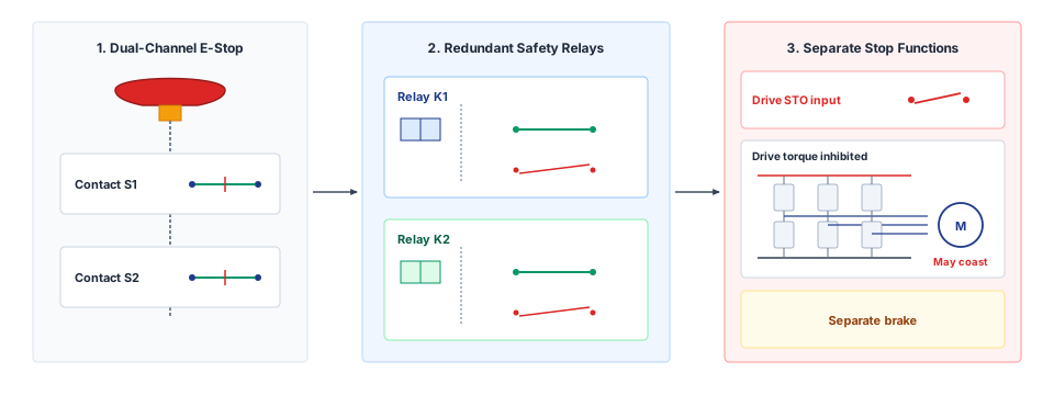
That separation between software control and hardwired, out-of-band trip circuits is not a stylistic preference. When the processor running the control loop stalls or corrupts its own state, only a physically independent path can still remove drive enable and clamp the brakes. The precedent that the lineage table of The Four Bedrock Laws attaches to the third law shows the cost of removing that hardware path and trusting software logic to gate a high-energy actuator on its own (war story 12.1).
War Story 12.1: Therac-25 software interlock elimination
Context: Between 1985 and 1987, the Therac-25 medical linear accelerator administered massive radiation overdoses to six cancer patients after system designers eliminated the electromechanical interlocks used in previous models, assigning safety-critical beam containment entirely to software (Leveson and Turner 1993).
Mechanism: Software race conditions and shared memory corruption in the operator interface allowed the machine to fire its high-current electron beam (25 MeV) without rotating the tungsten target and beam-flattening filter into position. Because the physical microswitches that previously interlocked beam activation had been removed, the underlying hardware possessed no independent means to detect that the operational mode conflicted with the turntable state.
Impact: Six patients received radiation doses estimated between 4,000 and 20,000 rads (up to 100 times the therapeutic level), causing severe tissue necrosis and three direct fatalities (Leveson and Turner 1993).
Response: Investigators mandated the restoration of independent hardware interlocks, requiring positive electromechanical verification of turntable configuration prior to beam generation, alongside formal software safety lifecycle standards.
Systems lesson: A software-based protection layer cannot serve as its own independent backstop. A runtime barrier filter may exercise binding authority over nominal control proposals, but the architecture still requires an out-of-band, physically independent trip mechanism to survive processor lockups, memory corruption, and firmware bugs. Moreover, because torque removal alone does not guarantee deceleration, the surviving physical response must match the plant’s dynamic envelope.
The four rungs run on two paths (figure 10). PROJECT, HOLD, and STOP run in safety MCU firmware at the 1 kHz tick and reach the drives through one arbiter, which selects a single actuation command \(\SelectedActuationCommand\); INHIBIT bypasses the firmware on a hardware path that removes gate-drive supply (STO) and drops spring-brake holding current when the processor itself fails. The rungs trade response latency, control authority, and recovery cost, and the arbiter selects directly among those whose entry prerequisites still hold. A controlled stop demands verified drive electronics and sufficient stopping clearance; losing drive integrity forces unpowered mitigation with strictly weaker physical guarantees. Selection is also only as sound as the state evidence behind it. The 2023 Cruise pullover, which When the Responsibilities Fail Together set beside Tempe as a failure after impact, selected a motion fallback on the strength of a missing track (war story 12.2).
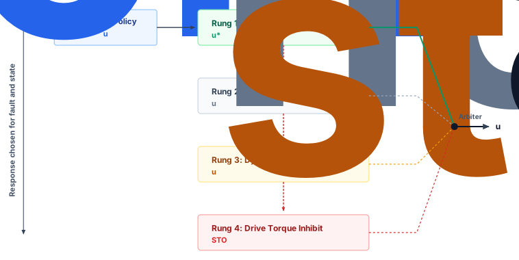
War Story 12.2: Cruise post-impact fallback (2023)
Context: In October 2023, an autonomous Cruise robotaxi in San Francisco encountered a pedestrian who had been struck by an adjacent human-driven vehicle and propelled into the robotaxi’s travel lane (Exponent, Inc. 2024).
Mechanism: The autonomous vehicle initiated an immediate emergency stop upon detecting the impact. However, the collision-classification subsystem erroneously localized the pedestrian to the side of the vehicle rather than under the chassis, categorizing the event as a side collision. The operational design domain for side collisions specified a secondary pullover maneuver to clear traffic. Because the perception pipeline had tracked the pedestrian only intermittently before the collision, the tracker marked the lane ahead as clear, prompting the vehicle to accelerate from standstill into the pullover (Exponent, Inc. 2024).
Impact: Executing the pullover dragged the pedestrian, who remained pinned beneath the vehicle’s floorpan, approximately 20 ft (6.1 m) at speeds reaching 7.7 mph (3.4 m/s), causing severe trauma (Quinn Emanuel Urquhart and Sullivan, LLP 2024). The California DMV subsequently suspended Cruise’s autonomous testing and deployment permits, prompting Cruise to halt fleet operations nationwide and recall software across 950 vehicles (California Department of Motor Vehicles 2023; Exponent, Inc. 2024).
Response: A post-collision fallback must prohibit renewed motion whenever state uncertainty persists. In this scenario, retaining a locked standstill and mandating physical inspection prevents the system from treating missing perceptual tracks as free space. Teleoperation feeds cannot substitute for verified local sensor coverage.
Systems lesson: An embodied fallback cannot infer free space from the absence of sensor tracks. Every transition across fallback states requires positive evidence verifying that assumed physical invariants hold, paired with failsafe physical restraints while state ambiguity remains unresolved.
Exponent, Inc. 2024. Cruise LLC–October 2, 2023, Incident Report. Exponent, Inc.
California Department of Motor Vehicles. 2023. DMV Statement on Cruise LLC Suspension.
Quinn Emanuel Urquhart and Sullivan, LLP. 2024. Report to the Boards of Directors of Cruise LLC, GM Cruise Holdings LLC, and General Motors Holdings LLC Regarding the October 2, 2023 Accident in San Francisco. Quinn Emanuel Urquhart; Sullivan, LLP.
12.8.2 Industrial stop categories and the safe torque off trap
On a moving mobile base or a gravity-loaded arm, Safe Torque Off (STO) is not an active brake: removing drive torque immediately leaves the base coasting on wheel momentum and lets the arm drop during the milliseconds before its mechanical friction brakes clamp. Decelerating the mobile manipulator safely instead uses closed-loop motor torque during the active braking phase and engages mechanical holding brakes only once the plant reaches confirmed standstill. Industrial standards distinguish machine-level stop categories from drive-level safety functions across this sequence. IEC 60204-1 classifies whether electrical power remains connected during and after deceleration. Functional safety standards such as IEC 61800-5-2 define the drive functions, including STO, SS1, and SS2, that execute individual stages of a response, and the HOLD and STOP rungs borrowed their names from them. Table 3 maps these formal classifications to their concrete physical obligations.
| Response | Motor torque and power | Physical stop obligation | Appropriate use |
|---|---|---|---|
| Admitted filtering | Drive remains active | Recheck the feasible kinetic barrier and tracking bound every tick | Nominal operation inside the validated envelope |
| Controlled hold (Category 2 / SS2-like) | Power remains for braking and hold | Verify stopping distance, thermal headroom, and static load support | Hold when feedback and torque authority remain available |
| Controlled stop then torque removal (Category 1 / SS1-like) | Power remains through deceleration; torque is removed afterward | Verify the full braking and transition time under load | Moving machine with enough reserved clearance |
| Torque removal (Category 0 / STO-like) | Drive cannot produce commanded torque; DC bus isolation is a separate function | A moving motor may coast; a separate brake or mechanical restraint needs its own timing and rating | State for which loss of torque has been shown safe |
12.8.3 Certified safety functions beneath the permission path
Citing an unrated numerical QP solver or software evidence-age check as the primary hazard control in a safety case fails certification audit immediately, because complex solver code without formal tool qualification and hardware diagnostic coverage cannot carry a safety integrity claim. In an embodied deployment, not all firmware executing the fallback ladder carries formal functional safety certification, so a certification engineer partitions software claims by the integrity of the underlying hardware substrate. On a production machine, formal guarantees rest primarily on a second, lower layer: dedicated safety functions in the motor drives, the optical safety scanner, and the arm’s safety controller, each architected and validated to a Performance Level (PL) under ISO 13849-1 (International Organization for Standardization 2023a). A Performance Level grades a safety function rather than a component, by the architecture category of its channels, their mean time to dangerous failure, their diagnostic coverage, and their defenses against common-cause failure (The Independence Requirement and the Two-Processor Hypothesis); IEC 61508 grades the same functions by Safety Integrity Level (SIL) (International Electrotechnical Commission 2010). These hardened functions substantiate the certified protective envelope. Above them, the MCU permission path operates primarily as an unrated performance layer designed to keep the learned policy inside the admissible set, preventing unnecessary trips of the hard safety floor. Only one narrow component of this MCU layer carries a safety rating, the watchdog that revokes authority when the chunk lease expires or the host heartbeat falls silent.
International Organization for Standardization. 2023b. ISO 3691-4:2023: Industrial Trucks, Safety Requirements and Verification, Part 4: Driverless Industrial Trucks and Their Systems. International Organization for Standardization.
International Organization for Standardization. 2025a. ISO 10218-1:2025: Robotics, Safety Requirements, Part 1: Industrial Robots. International Organization for Standardization.
Table 4 maps each response and speed channel onto its certified industrial counterpart. The core drive functions derive from IEC 61800-5-2 (International Electrotechnical Commission 2016b): safe torque off (STO), safe stop 1 (SS1), safe stop 2 (SS2), safe operating stop (SOS) (which monitors standstill), safely limited speed (SLS), and safe brake control (SBC) (which drives the mechanical brake coil through a monitored output). For the mobile base, ISO 3691-4 assigns required performance level (PLr) d to braking system control and personnel detection within the travel path, while assigning PLr b to the electromechanical parking brake (International Organization for Standardization 2023b; TÜV Rheinland 2021). For robotic manipulators, ISO 10218-1:2025 classifies systems into Class I (manipulator mass under 10 kg with strictly limited force and velocity) and Class II, mandating PL d (or SIL 2) across all safety functions on Class II arms (International Organization for Standardization 2025a; Hartmann et al. 2026). Because the warehouse arm weighs 18 kg, it is governed by Class II mandates.
| Response or channel | Certified counterpart | Governing requirement | Required level on this machine |
|---|---|---|---|
PROJECT, feasibility, evidence-age |
None; the admission checks are not claimed as safety rated | None | None claimed; recorded as a premise |
| Lease expiry and heartbeat loss | MCU watchdog that commands STO or SS1 on the drives | ISO 13849-1; IEC 61508 for the MCU firmware | Set by the risk assessment for the stop it triggers |
| Base aisle-speed ceiling | SLS on the drive wheels, switched by the scanner’s field set | IEC 61800-5-2; speed control under ISO 3691-4 | Set by ISO 3691-4 and the risk assessment |
| Person at the rack end | Scanner protective field that selects STOP |
ISO 3691-4 person detection; ISO 13855 field sizing | PL d |
STOP on the base |
Ramp-monitored SS1 (SS1-r), then parking brake | IEC 61800-5-2; ISO 3691-4 braking control | PL d for braking control; PL b for parking brake |
HOLD |
SS2 into SOS | IEC 61800-5-2 | PL d on the arm; base set by the risk assessment |
INHIBIT |
STO with SBC | IEC 61800-5-2; IEC 60204-1 Category 0 | PL d on the arm; base as for braking control |
| Arm TCP, latch, and handover limits | Safety-rated monitored speed in the arm’s safety controller | ISO 10218-1:2025 | PL d (Class II) |
| Handover to the coworker’s hand | Speed and separation monitoring or power and force limiting | ISO 10218-2:2025 | Set by the application risk assessment |
As the first row of table 4 indicates, the online CBF-QP, feasibility tests, and sensor evidence-age checks operate without formal safety ratings. Consequently, safety cases cannot cite these complex numerical filters as certified protective measures; instead, the enforcement record treats their correct execution as an operational premise. System architects face two choices when structuring this boundary. An engineering team can treat all MCU-level admission checks strictly as an unrated performance layer, relying entirely on the certified hardware floor to prevent harm. Alternatively, the team can certify the entire MCU firmware stack to functional safety standards (such as IEC 61508 or ISO 26262), subjecting matrix solvers and barrier algorithms to exhaustive formal methods, tool qualification, and deterministic execution bounds.
The running machine assumes the hybrid path. Its qualified watchdog, the table’s second row, independently commands STO or SS1 at the drive level when the chunk lease expires or the host heartbeat falls silent. Its bounded scope reduces the qualification burden, while isolation, failure behavior, timing, and lifecycle evidence remain necessary. Meanwhile, the complex admission checks remain unrated, leaving the certified optical scanner and drive-integrated safety functions to handle primary hazard mitigation. This split architecture demands strict physical and temporal isolation between the rated watchdog and unrated solver routines to eliminate common-cause faults.
↪ How the release case treats the certified watchdog as a rated safety function and the unrated admission checks as empirical premises is developed in The standards map for the running machine.
International Organization for Standardization. 2025b. ISO 10218-2:2025: Robotics, Safety Requirements, Part 2: Industrial Robot Applications and Robot Cells. International Organization for Standardization.
International Organization for Standardization. 2016. ISO/TS 15066:2016: Robots and Robotic Devices, Collaborative Robots. International Organization for Standardization.
Hartmann, Daniel, Kristýna Hamříková, Aleš Vysocký, Vendula Laciok, and Aleš Bernatík. 2026. “Evolution of Safety Requirements in Industrial Robotics: Comparative Analysis of ISO 10218-1/2 (2011 Vs. 2025) and Integration of ISO/TS 15066.” arXiv Preprint arXiv:2602.17822.
Marvel, Jeremy A., and Rick Norcross. 2017. “Implementing Speed and Separation Monitoring in Collaborative Robot Workcells.” Robotics and Computer-Integrated Manufacturing 44: 144–55. https://doi.org/10.1016/j.rcim.2016.08.001.
The robotic arm introduces collaborative operational modes beyond those required by the mobile base. Speed and separation monitoring (SSM) continuously modulates or halts arm velocity to maintain a protective clearance envelope around human workers, while power and force limiting (PFL) caps transient and quasi-static contact forces during intentional physical collaboration. Standard ISO 10218-2:2025 incorporates the collaborative requirements previously defined in ISO/TS 15066 (International Organization for Standardization 2025b, 2016). The 2025 standard formalizes SSM within section 5.14.5 and normative Annex L, and specifies PFL limits across anatomical regions in section 5.14.6 and informative Annex M (Hartmann et al. 2026). The protective separation distance is governed by: \[\ProtectiveSeparationDistance = \PersonApproachTravel + \RobotReactionTravel + \RobotStoppingTravel + \IntrusionDistance + \PersonPositionUncertainty + \RobotPositionUncertainty,\] where \(\PersonApproachTravel = \HumanWalkingSpeedBound (\RobotReactionTime + \StoppingDuration)\) represents worker displacement during robot reaction latency \(\RobotReactionTime\) and stopping duration \(\StoppingDuration\). Next, \(\RobotReactionTravel = \RobotApproachSpeed \RobotReactionTime\) is robot displacement prior to brake onset, and \(\RobotStoppingTravel\) is the physical braking distance. The term \(\IntrusionDistance\) is the penetration distance permitted by sensor resolution. Finally, \(\PersonPositionUncertainty\) and \(\RobotPositionUncertainty\) denote positional uncertainties for the human and robot, respectively (Marvel and Norcross 2017).
Evaluating this expression for the descending arm highlights the relative weight of human vs. robot motion. The ISO 13855 human approach speed is \(\HumanWalkingSpeedBound =\) 1.6 m/s (International Organization for Standardization 2024). The vision-path latency is \(\RobotReactionTime =\) 133.6 ms, and the tool-center-point velocity is \(\RobotApproachSpeed =\) 0.96 m/s. The gravity-biased joint deceleration from section 12.3 completes in \(\StoppingDuration =\) 166 ms across \(\RobotStoppingTravel =\) 79 mm. With these values, the human displacement term is \(\PersonApproachTravel =\) 479 mm and the robot reaction displacement is \(\RobotReactionTravel =\) 128 mm. Together, these preliminary dynamic components total 686 mm before accounting for sensor intrusion margin \(\IntrusionDistance\) and spatial uncertainties \(\PersonPositionUncertainty\) and \(\RobotPositionUncertainty\).
International Organization for Standardization. 2024. ISO 13855:2024: Safety of Machinery, Positioning of Safeguards with Respect to the Approach of the Human Body. International Organization for Standardization.
Human movement accounts for 70 percent of this cumulative margin. Just as in the walking-person stopping budget of section 12.2.1, human velocity during the combined reaction and deceleration phases dominates the required clearance. Against an approaching human, total stopping duration imposes a far heavier spatial tax than the robot’s physical braking distance alone. Because standard vision pipelines lack functional safety ratings, a certified SSM implementation must use dedicated, safety-qualified sensors to measure separation and bound \(\RobotReactionTime\).
The standards distinguish how they treat obstacle velocity. Standard ISO 3691-4 specifies detection assuming a stationary person standing in the travel path (TÜV Rheinland 2021); consequently, vehicle testing protocols evaluate protective envelopes against the static-obstacle formulation of equation 1. If a worker continues walking toward the vehicle throughout the braking sequence, the relative closing velocity exceeds the standard’s baseline assumptions. In contrast, SSM explicitly models dynamic human approach velocity (\(\HumanWalkingSpeedBound\)), explaining why mobile base navigation requires an explicit aisle-crossing protocol whereas robotic manipulation requires an active separation or contact-limiting channel. For collaborative handoffs, the enforcement record adopts the standardized biomechanical model of the human hand, distinguishing between unconstrained (transient) and clamped (quasi-static) contact scenarios. While simplified models often approximate PFL as a single lumped elastic collision with a fixed force threshold, ISO 10218-2 specifies distinct permissible force and pressure ceilings across individual anatomical regions. A complete architectural map correlating each subsystem, governing regulatory standard, and validation artifact is synthesized in the release decision framework (Standards map for the warehouse mobile manipulator (as of 2026)).
TÜV Rheinland. 2021. ISO 3691-4:2020: A Standard for Automated Guided Vehicles. White paper.
Checkpoint 12.3: Choosing the physical fallback
Before selecting a defensive fallback strategy, review the requirements governing state-dependent stopping modes, safety functions, and timing reserves:
12.9 Runtime Enforcement Failure Modes
Every guarantee in this chapter has rested on premises about the computer that runs the filter and the plant it models: a held-up logic rail, a bounded cycle, a credible deceleration, and a bus that delivers the admitted command on time. On the warehouse mobile manipulator each of those premises already carries a concrete spatial price. A missed tick costs 1.3 mm of travel at the aisle speed. A lease honored by the host instead of the MCU turns a 200 ms planning stall into 182 mm of unbraked travel and a 50.99 mm overrun. An unprotected integrator spends 195 mm against a 131.0 mm spare. Gravity on the arm and mug takes 75 percent of the joint’s peak torque and quadruples the descending stop. Runtime enforcement failures trace back to four classes, one for each premise:
- Common-cause infrastructure failures: When the learned policy and the safety filter share power rails, clock sources, reset lines, or thermal paths, one fault can disable both. A current surge during hard acceleration can sag a shared supply until it resets both the neural accelerator and the microcontroller that monitors it, and a shared reset or clock fault can silence the monitor at the instant the policy issues an errant command. The running machine therefore holds its permission logic on an isolated, held-up rail (section 12.8.1).
- Timing overruns and execution jitter: A quadratic program that stalls on an ill-conditioned active set, or a filter scheduled on a non-deterministic operating system, spends braking clearance while it computes. An overrunning routine cannot be trusted to detect its own stall, which is why the declared 250 \(\MicroUnitPrefix\text{s}\) cycle comes with a qualified preempting timer or independent mechanism that selects the resident fallback when a deadline expires (section 12.6.4).
- Plant mismatch and unobservable state drift: The filter evaluates safety against a model. A floor film that lowers friction, a payload that shifts the center of mass, or winding heat that lowers peak torque removes control authority the model still credits, so the solver can admit a deceleration the hardware cannot deliver. Where onboard sensors cannot observe the shift, the safe set must carry qualified uncertainty margins or the operating domain must restrict speed, as the complete optimistic inspected-floor screen falls to 1.17 m/s, before driven-wheel load share and available braking are qualified (section 12.2).
- Interconnect contention and transport delays: State reads and command writes must cross physical buses. Unprioritized telemetry or logging can queue a joint reading until it is stale, or hold a filtered command in a transmit queue while the drive keeps executing the previous high-speed setpoint. The running machine carries its admitted command in a cyclic EtherCAT frame (stage 5 of the cycle budget) and charges the board link to the dispatch-to-admission budget.
None of the four yields to a better solver or an automotive-grade microcontroller. Each is answered by evidence. Common causes and contention need isolation and bounded interference, which Workload Placement tests on silicon. Overruns need a verified execution bound with an independent fallback. Plant mismatch needs worst-case rather than nominal parameter margins. All four need a record of every enforcement decision, with its solver latency, active constraints, and sensor timestamps, so that an incident can be traced to the policy, the plant, or the infrastructure.
12.10 The Enforcement Record
When a warehouse mobile manipulator halts at a rack end because runtime safety logic rejected a motion proposal, forensic analysis requires unambiguous provenance: which threshold failed, which physical detector measured the violation, and which fallback rung took control of the actuators. The enforcement record is the tenth record in the record chain, the point where offline characterization meets online execution. It formalizes runtime safety across three cooperating artifacts:
- Enforcement contract: The signed, immutable specification compiled into microcontroller firmware that fixes qualified tracking bounds \(\TrackingErrorBound\), barrier coefficients, timer deadlines, delivered-effort error and response-delay bounds, and fallback routing tables before deployment.
- Admitted command: The record’s per-tick output. On each millisecond control cycle, the microcontroller gatekeeper generates an admitted command for transmission across the causal boundary. This payload contains the admitted or projected control \(\CertifiedControlAction\), the verified barrier margin \(\BarrierFunction(\MechanicalPlantState)\), tracking error validation \(\TrackingErrorDistance(\TimeInstant) \le \TrackingErrorBound\), and the remaining hardware lease. The gatekeeper forwards only the bare setpoint and protective envelope to the motor drives, committing the complete supervisory state to the audit log.
- Enforcement audit log: The high-rate forensic stream that captures per-tick proposal evaluations, intervention vectors \(\FiniteChange \ControlInput = \CertifiedControlAction - \NominalControlCommand\), quadratic programming (QP) solve latencies, and veto events in non-volatile storage.
Together, these artifacts render safety decisions fully auditable without burdening the actuator bus. The contract predefines the admissible operating envelope, the admitted command tags the immediate actuator setpoint, and the audit log preserves the causal chain of evidence. Real-time enforcement depends entirely on the protected command path, deterministic loop timing, and verified physical braking capabilities.
12.10.1 The admitted command schema
If the gatekeeper emits a bare torque vector without a monotonic sequence counter, a digest of the admitted parent trajectory, or the remaining lease duration, a replayed frame or a stalled microcontroller cannot be distinguished from a live command, and a post-incident audit cannot reconstruct which safety margins were checked on that millisecond tick. At each control cycle, the gatekeeper therefore produces an admitted command that establishes runtime authority at the drive interface (table 5). Its fields explicitly bind the actuator setpoint to its parent trajectory, verified safety margins, and active fallback state. Because each entry records a decision made under assumed physical conditions, runtime containment still relies on those assumptions matching physical reality.
| Field Name | Type & Units | Physical System Invariant & Validation Rule | Mobile Manipulator Parameter / Value |
|---|---|---|---|
token_sequence_id |
uint64_t (counter) |
Monotonically increasing admitted-command ID on MCU clock | Increments every 1 ms tick |
timestamp_mcu_ns |
uint64_t (ns) |
Absolute MCU monotonic timestamp of admission | Latch instant at causal boundary |
parent_trajectory_digest |
uint8_t[32] (SHA-256) |
Cryptographic link to the admitted trajectory record and chunk lease | SHA-256 of active trajectory record |
admitted_control_vector |
float32[N_act] (N·m) |
Filtered torque \(\CertifiedControlAction\) realized only under the qualified effort-error and response-delay contract; nominal if safe, projected if near boundary | Per-axis qualified torque envelope; 87 N·m only for the characterized arm axis |
intervention_vector |
float32[N_act] (N·m) |
Intervention delta \(\FiniteChange \ControlInput = \CertifiedControlAction - \NominalControlCommand\); zero when the admitted command equals the nominal command | Nonzero only during CBF-QP projection |
barrier_margin |
float32 (normalized) |
Dimensionless \(\BarrierFunction(\MechanicalPlantState)/\BarrierNormalizationScale\) with positive scale and barrier identity bound in the contract | Must satisfy \(\BarrierFunction(\MechanicalPlantState) \ge 0\) |
tracking_error |
float32 (m) |
Instantaneous tracking error norm \(\TrackingErrorDistance(\TimeInstant) = \lVert \MeasuredTrackedPosition - \ReferencePosition \rVert\) | Base position error: \(\TrackingErrorDistance(\TimeInstant) \le\) 40 mm; arm channels use their own qualified bounds |
active_fallback_rung |
uint8_t (enum) |
Active execution state: PROJECT, HOLD, STOP, INHIBIT |
0x01 (PROJECT) during nominal tracking |
lease_remaining_ns |
uint32_t (ns) |
Remaining validity duration of current chunk lease | Trips STOP / HOLD upon reaching zero |
crc32_token |
uint32_t (checksum) |
CRC-32 over the log entry, for audit integrity | Log reader rejects a corrupt entry; the drive-facing setpoint carries its own safety-layer CRC |
Constructing the enforcement record synthesizes four upstream records across the offline and runtime evidence strands, where the offline strand establishes physical plant capabilities and empirical policy competence while the runtime strand tracks live execution state. From the runtime strand, the trajectory record of The Trajectory Record supplies the admitted reference and its precomputed, dynamically feasible stop suffix. From the offline strand, the evaluation record of The Evaluation Record provides runtime monitor specifications and the empirical coverage-gap catalog that define the active supervisory channels. The policy manifest of The Policy Manifest defines the declared ODD so that the enforcer’s validity region is restricted to well-sampled operating regimes. The limit records of Measuring a Machine's Own Limits establish empirical braking rates, actuator onset delays, and torque envelopes alongside their operating preconditions. To these upstream parameters, the enforcement record contributes the formal guarantees of the gatekeeping pipeline. These are the qualified tracking bound \(\TrackingErrorBound\) and the stopping metrics (\(\StoppingDuration, \StoppingDistance\), which bound the duration and displacement required to arrest plant momentum). They also include the control barrier function coefficients, the discrete execution period, the per-check thresholds mapped to fallback-ladder rungs, and the dynamic validity boundary.
The parent_trajectory_digest binds each admitted command to its originating trajectory and active chunk lease, providing forensic traceability back to the planner’s proposal. Digests bind content for integrity checks; sequence counters and monotonic freshness checks reject stale or replayed commands within the protected drive interface. Sender authenticity additionally requires an authenticated channel or message authentication. Similarly, the lease_remaining_ns field conveys remaining execution authority, but this parameter guarantees safety only when the drive firmware actively enforces lease expiration by triggering a deterministic physical fallback. Streaming these fields to the audit log, alongside nominal proposals, intervention deltas, barrier margins, tracking errors, and solver latencies, gives engineers the causal evidence needed to reconstruct anomalous behaviors within the temporal resolution of the sensor pipeline.
This division of responsibilities dictates an architectural split at the fieldbus boundary. Motor drives have no operational need for trajectory digests or barrier margins; they require immediate setpoints, current limits, and active fallback commands delivered with fail-safe transport guarantees. Industrial systems handle this through established safety bus architectures. For example, Safety over EtherCAT (FSoE) implements the black-channel principle, treating the underlying communication bus as inherently untrusted (International Electrotechnical Commission 2021). FSoE encapsulates drive commands within a safety container featuring dedicated cyclic redundancy checks (CRCs), unique connection identifiers, strict sequence counters, and independent watchdog timers. These measures detect communication faults; sender authentication against malicious traffic requires a separate security mechanism. When a communication watchdog expires, the drive autonomously engages its safe stop state without waiting for microcontroller intervention. The rich diagnostic context (digests, barrier margins, intervention vectors, and solver runtimes) streams to the audit log instead. An ad hoc safety-communication scheme for drive control must independently justify the fault detection and response properties covered by established functional-safety standards.
International Electrotechnical Commission. 2021. IEC 61784-3:2021: Industrial Communication Networks, Profiles, Part 3: Functional Safety Fieldbuses, General Rules and Profile Definitions. International Electrotechnical Commission.
↪ The authority record’s per-tick entries, which log the ladder rung of any active fallback, are developed in Per-tick evidence tuples and the fault injection suite.
Filled in for the warehouse mobile manipulator, the enforcement record fixes the base’s stopping parameters at the rack end alongside the arm’s validity region and monitoring channels at the doorway and packing station. The tracking bound \(\TrackingErrorBound\) is 40 mm (matching row 7 of table 1), and the resident stopping trajectory is the jerk-limited S-curve suffix, which takes 931.25 ms and covers 605.31 mm from the 1.3 m/s aisle speed, or 1,031.25 ms and 773.44 mm from the 1.5 m/s drive limit. These spatial bounds are evaluated on a 1 ms loop period with a declared WCET of 250 \(\MicroUnitPrefix\text{s}\) inside a 400 \(\MicroUnitPrefix\text{s}\) deadline, supervised by three parallel timers: the 60 ms chunk lease, the 100 \(\text{Hz}\) host heartbeat with its 30 ms silence timeout, and the 5 ms hardware watchdog.
For the manipulator, the validity region governs both the doorway and the packing station. The baseline door policy matches the nominal target ODD of the evaluation record (the nominal plate, standard door resistance, a stationary base, and the guarded approach, whereas the recovery update analyzed in Qualifying a recovery update qualifies the displaced-plate cell under its own distinct record rather than expanding the baseline region). The packing station admits picking a mug from the conveyor under a live intent lease followed by coworker handover. Across these zones, manipulator monitoring channels enforce dynamic velocity ceilings at the TCP. Inside the door zone, the approach-speed channel from the evaluation record’s runtime_monitor_specs caps tool velocity at 0.03 m/s, whereas in unconstrained space the conveyor mug pick operates under the nominal 1 m/s free-space TCP limit. While a coworker holds accept_item (Human Authority, Reaction Time, and Clearance), a handover channel engages before the separating distance closes to the arm’s biased stop plus its blind-travel displacement and caps the approach toward the coworker’s hand at 0.10 m/s, well below the 0.24 m/s contact-force ceiling for a free hand capable of recoil. Because a hand trapped against a rack upright or structural link permits an impact speed of at most 0.053 m/s, this handover cap is valid only when physical workstation geometry provably precludes clamping (section 12.6.2), a condition that the release argument must substantiate.
For the mobile base, operating assumptions distinguish between nominal and low-friction surfaces, each carrying its own cryptographic digest in the release manifest. The standard configuration requires a qualified directional braking lower bound encompassing driven-wheel load share, traction, torque, and stability, where a friction coefficient of at least 0.204 serves only as a necessary optimistic all-weight screen rather than sufficient evidence that the design deceleration holds. By contrast, a restricted configuration accommodates degraded traction down to an inspected-floor friction of 0.12. The restricted illustration stipulates that its 1.177 m/s² braking rate is available (since inspection alone does not establish that lower bound), and its deceleration suffix uses that stipulation to stop in 1015.3 ms across 507.6 mm from 1 m/s beneath the 1.17 m/s complete inspected-floor screen, whose braking premise still requires qualification.
Each base entry incorporates the 63.3 ms dispatch-to-admission allocation and its own scenario-specific remaining clearance. The 48.7 mm stopping reserve belongs to the dry static-obstacle aisle candidate; the restricted configuration must recompute its reserve from its own speed and braking rate. Because this allocation represents an analytical budget, neither configuration is certified for admission until physical deceleration measurements under maximum payload confirm the modeled margin.
Each numerical entry in the record carries the evidence category of its limit record: measured, derived, datasheet, or illustrative. These categories reflect fundamentally different degrees of operational confidence. The base’s 931.25 ms stopping time, for instance, is a derived value. It follows mathematically from the geometry of the S-curve suffix under a stipulated jerk bound and an illustrative deceleration figure, assuming that motor drives faithfully deliver commanded current and tires maintain continuous traction. Only loaded stopping trials on the actual operating surface establish a measured value. Physical tests reveal empirical non-idealities that escape closed-form derivations, including electromechanical brake onset scatter, structural compliance, and surface contamination. Even then, empirical data supports a formal bound only when combined with worst-case fault models and defined operating limits. Explicitly recording the evidence category prevents an integrator from mistaking a derived stopping estimate for a verified hardware limit.
The record also carries the routing of section 12.8 as part of its contract. An arriving proposal can neither renew an active command nor revoke its authority merely by being transmitted, and each lease or heartbeat expiry, cycle loss, or bus undervoltage selects the rung that matches the machine’s state and the hardware that survives. Every field of the record is either an integrity token or an operational threshold evaluated against live execution state. These checks examine the proposal’s sequence counter and checksum, its stored dispatch age against 51.8 ms, reconstructed perception latency against validity and stopping-margin criteria, active elapsed time against the chunk lease, tracking error against the allowable envelope \(\TrackingErrorBound\), joint-velocity and torque-slew ceilings, barrier margins, phase-current and bus-voltage limits, and hardware watchdog timeouts. The contract binds each threshold to the independent sensing hardware that measures it and to the specific fallback rung selected upon violation. Table 6 organizes these rungs by residual system authority and specifies the hardware timer that triggers each transition.
↪ Byte layout: The enforcement record’s fields, types, and units are given in Enforcement record.
| State | Trigger and authority | Timing check | Physical response to validate |
|---|---|---|---|
PROJECT |
Fresh proposal, healthy heartbeat, feasible kinetic barrier; an invalid replacement is refused; active setpoints continue only while their own evidence, lease, state, and stop reserve remain valid | 1 ms cycle; declared full-cycle WCET 250 \(\MicroUnitPrefix\text{s}\) inside a 400 \(\MicroUnitPrefix\text{s}\) deadline | Track admitted torque within qualified error and brake reserve |
HOLD |
At standstill, active elapsed time beyond the 60 ms lease, host heartbeat silent beyond 30 ms, while powered support remains available | Expiry detected on the MCU clock within one tick | Powered support against gravity and payload; on undervoltage, secure qualified restraint before support expires |
STOP |
In motion, lease or heartbeat expiry, shared-rail undervoltage, tracking error beyond \(\TrackingErrorBound\), an empty feasible control set, or a tripped disturbance observer or solver deadline, while powered braking remains available | Include detection, dispatch, drive rise, and brake response | Resident stop on the base, state-matched stop on the arm; measured stop distance under load; no claim after viability is lost |
INHIBIT |
Independent wired supervisor or external trip detects MCU cycle loss | Assumed 5 ms detection plus measured drive, contactor, or brake response | STO removes motor torque and the spring brakes set after coil decay; unbudgeted, so no stopping claim rests on it |
Because runtime safety guarantees require that plant dynamics remain inside the modeled operational envelope, the enforcement record bounds execution within an explicit validity region. The manipulator’s doorway speed ceiling illustrates how empirical evidence defines these bounds. The policy’s proposed 0.10 m/s approach, refused in section 12.5 on evidential and physical grounds, passes only the narrowest timing test, since its 2.5 ms unbraked compression time from first contact to the latch force limit exceeds the 2 ms contact-loop cycle. That naive unbraked deadline ignores both the force already accumulated before the tripwire fires and the compression distance the arm still needs to decelerate to rest, so the record keeps both grounds for refusal beside that pass, the post-trip stop that section 12.6.2 sized and the absence of trials at that speed, ensuring that no reader mistakes the timing pass for admission. The enforcer therefore clamps the command to the 0.03 m/s evidence-based ceiling, evaluates full contact dynamics, and records the active constraint in the audit log. In contrast, the coworker handover ceiling is derived from the structural impact model (equation 13), which caps approach velocity below the contact-force limit where modeled impact forces meet allowable biomechanical thresholds for an unconstrained hand. Faster proposals are projected onto this boundary and logged as intervention vectors.
When onboard estimators detect a state outside the validity envelope, such as an undeclared payload mass, the supervisory monitor flags the violation, revokes policy authority, and commands a state-matched stop. Environmental conditions that lack direct onboard sensing, however, cannot trigger dynamic runtime vetoes. Surface friction at the wheel-floor interface represents an unobservable state, because mobile bases carry no transducers to measure instantaneous traction coefficients beneath their wheels. Consequently, the standard configuration relies on verified floor friction as an operating precondition, while low-friction operations require manual floor inspection and commissioning of the restricted configuration.
↪ The floor-friction premise is enforced as an entry of the residual-claims register in A residual-claims register.
An enforcement record connects proposed neural trajectories to validated physical invariants, operational thresholds, and deterministic fallback responses. Algorithmic correctness, however, cannot compensate for an execution platform that violates its timing or braking commitments under load. An enforcer whose control barrier functions are mathematically verified will still fail if the couplings it still shares with the host, the board-link DMA into its memory, a supply rail, or a clock, delay its cycle under load during high-speed transit. In physical artificial intelligence, safety failures manifest in the time domain just as decisively as in algorithmic logic.
12.11 Fallacies and Pitfalls
A physical safety filter prevents collisions only as long as its control loop meets hard real-time execution deadlines and its state feedback accurately reflects reality. Safety qualification cannot rely solely on evaluating nominal control barrier equations under idealized laboratory conditions; real systems fail when host processors lock up, state estimators drift, or perception pipelines misclassify obstacles. Production testing must therefore exercise system response precisely when these core execution and sensing assumptions break down.
Pitfall: Assuming high-level policy computers can be relied upon to execute graceful shutdown.
A software exception handler on an application processor cannot arrest physical momentum when the operating system kernel panics. Consider a warehouse mobile manipulator whose high-level application processor experiences an operating system kernel panic while navigating an aisle at 1.3 m/s. Once the host kernel crashes, it can no longer generate deceleration trajectories or dispatch motor setpoints. Cutting the drive enable line to zero torque is equally hazardous, leaving the unbraked base to coast under momentum directly into the aisle racks. Relying on an operating system shutdown handler or a user-space exception hook assumes that the host software stack remains functional, an assumption that fails during kernel panics, hardware lockups, or memory exhaustion. Physical fail-safety requires stopping clearance and torque authority that persist independently of the host. In a robust architecture, the downstream MCU detects the missing heartbeat within its 30 ms timeout, comfortably within the stopping budget’s reserved lease margin. The MCU then immediately executes its resident jerk-limited stop suffix, decelerating the base to a complete stop in 931.25 ms across 605.31 mm. While host shutdown routines manage orderly transitions during routine operation, true fault tolerance demands that stopping authority resides in hardware and low-level firmware that survive host death.
Architect’s countermeasure: Decouple physical stopping authority from host processor lifecycles with two MCU timers that the host cannot service on the MCU’s behalf. The heartbeat timer, refreshed by the host’s periodic heartbeat, catches a host that has gone silent, which is what a kernel panic produces. The chunk lease, refreshed only by a valid admitted proposal, catches a host that is still alive and still sending heartbeats but no longer delivering valid motion. When either expires, the MCU intervenes without waiting for host acknowledgment, selecting the precompiled, state-matched stop suffix within its validated entry envelope and actively commanding motor torques to bring the robot to a controlled halt.
Fallacy: A mathematically correct safety filter guarantees safety even when underlying state feedback has drifted.
A barrier certificate evaluated against a drifted or corrupted state estimate provides zero physical protection. The mobile base’s 40 mm tracking certificate bounds true physical position error only under qualified state feedback assumptions. In practice, comparing the reference trajectory against encoder-reported position serves merely as a runtime proxy; that agreement alone cannot verify the actual physical bound. Wheel slip or an optical encoder with an undetected scale bias can lead the state estimator to report that the base is farther from the aisle rack than its true physical location. The CBF-QP solver then easily satisfies its barrier inequality on the corrupted estimate, while the physical base exhausts clearance margins that the stopping budget never granted. Only an independent sensing channel, such as an IMU or a safety lidar measuring direct range to the rack, can expose this divergence, and only if the tracking error exceeds the diagnostic monitor’s observability threshold. System qualification must bound how far the estimate can drift before detection occurs. The stopping budget must account for this worst-case drift in its localization allowance \(\LocalizationBound\), rather than crediting that same uncertainty to the dynamic tracking inset. To preserve formal safety guarantees, the qualification framework must explicitly document which physical error source each budget allowance covers.
Architect’s countermeasure: Implement redundant, heterogeneous sensor cross-checks that continuously validate kinematic wheel odometry against independent physical channels, such as optical flow, time-of-flight lidar, or secondary motor encoders. Expand the safety filter’s localization allowance \(\LocalizationBound\) to absorb the maximum unobservable drift that can accumulate before diagnostic cross-checks trip, guaranteeing that the contracted safe set remains physically invariant even under worst-case sensor degradation.
Pitfall: Coupling safety braking authority to stochastic semantic classification rather than deterministic spatial clearance.
Emergency stopping authority must be bound to deterministic spatial clearance rather than upstream semantic classification. When an automated vehicle conditions collision avoidance on object classification and trajectory forecasting, perception errors can silently disable emergency intervention. The March 2018 Tempe collision, analyzed in When the Responsibilities Fail Together, shows the sequence (figure 11). Although the developmental automated driving system (ADS) first detected the pedestrian pushing a bicycle 5.6 s before collision, repeated perception toggling between vehicle, other, and bicyclist classifications reset the tracking filter, discarding historical motion at each switch and treating the obstacle as an unpredicted static entity (National Transportation Safety Board 2019, sec. 1.5.5.2). When the pipeline finally registered an imminent crash 1.2 s before impact, high-level policy suppressed actuator intervention for a full 1-second delay to avoid vehicle swerving, after which the planner issued only a gradual deceleration request. The architectural failure sits at the base of the timeline. The vehicle’s factory-installed Volvo autonomous emergency braking (AEB) interlock had been suppressed during ADS operation. An independent geometric safety barrier avoids these cascading failures by separating spatial clearance from semantic inference. It commands an emergency stop based solely on physical distance and closing speed, regardless of what label the neural perception pipeline assigns to the obstacle.
Architect’s countermeasure: Enforce the causal separation of perception and safety by establishing an independent, non-semantic geometric barrier. A safety-rated sensor channel, such as a time-of-flight lidar curtain, radar, or safety scanner, must maintain direct hardware veto authority to command a Category 1 stop. This safety layer evaluates occupancy and closing rate directly, completely bypassing the neural perception pipeline, semantic classifiers, and trajectory forecasting models.
National Transportation Safety Board. 2019. Collision Between Vehicle Controlled by Developmental Automated Driving System and Pedestrian, Tempe, Arizona, March 18, 2018. HAR-19/03. National Transportation Safety Board.
Fallacy: Assuming a continuous-time barrier certificate holds under discrete Zero-Order Hold sampling without an inter-sample kinematic buffer.
Checking a continuous-time barrier inequality at discrete sampling instants does not guarantee inter-sample safety. In digital control architectures, an actuator applies a constant torque or current command over the entire zero-order hold (ZOH) interval \(\PermissionLoopPeriod =\) 1 ms. If an active-set QP solver computes a minimally invasive control input at sample \(\TimeInstant_k\) that places the plant directly on the boundary of the safe set (\(\SafetyBoundaryManifold\)), continuous physical dynamics unfold during the intervening hold period. Between \(\TimeInstant_k\) and \(\TimeInstant_{k+1}\), physical acceleration under the held actuator command can drive the true state across the boundary before the next control cycle executes. Equating a continuous barrier certificate \(\BarrierFunctionRate + \LinearBarrierDecayRate \BarrierFunction \ge 0\) directly with discrete-time invariance without an inter-sample buffer invites boundary violations whose severity grows with velocity and sample period.
Architect’s countermeasure: Contract discrete-time barrier certificates by the worst-case inter-sample kinematic drift buffer, \(\FiniteChange \ZohHoldTravel = \BodySpeed \PermissionLoopPeriod + \frac{1}{2} \ProfileAccelerationBound \PermissionLoopPeriod^2\) evaluated at the highest reachable speed \(\BodySpeed\). In a 1 kHz control loop operating at the 1.5 m/s drive limit with an independently stipulated approach-acceleration upper bound of 2 m/s², this inter-sample displacement bound equals 1.501 mm, the drift that the discretization condition of section 12.6.3 charges. Enforcing the barrier condition against the tightened safe set \(\TightenedDiscreteSafeSet = \{\MechanicalPlantState \mid \BarrierFunction(\MechanicalPlantState) \ge \FiniteChange \ZohHoldTravel\}\) preserves physical clearance throughout the hold duration when the barrier measures spatial distance. When accounting for this margin in the stopping budget, architects must avoid double-counting, because any travel already allocated to the budget’s one-tick fault detection interval already covers this displacement. Furthermore, when evaluating non-spatial or kinetic barriers, engineers cannot rely solely on a geometric displacement bound; the implementation must bound the worst-case evolution of the barrier function itself under the held input across the full sample interval \([\TimeInstant_k, \TimeInstant_{k+1}]\).
12.12 Summary
Runtime enforcement grants an admitted plan continuing, conditional permission to drive physical hardware. On every control cycle the enforcer evaluates live plant state against the tracking bound, the stopping reservation, and the actuator authority that remains. It passes a safe proposal through, projects a correctable one back into the admissible set, and selects a resident fallback, without waiting for the learned proposer, when no correction exists or the proposer falls silent.
Clearance is a composite margin, not a distance read from a map. At the warehouse mobile manipulator’s 1.3 m/s aisle speed, travel during the pre-brake delay \(\PrebrakeDelay\) takes 173.68 mm, the \(\DifferentiabilityClass^2\) stop suffix 605.31 mm, localization and protective margin 150 mm, and the tracking inset 40 mm, for 968.99 mm of the 1.10 m available at the rack end. The remaining 131.01 mm pays for dispatch-to-admission travel (\(\SpeedAtDetection\DispatchAdmissionInterval =\) 82.3 mm) and leaves a 48.7 mm reserve, so the aisle speed remains a candidate until loaded timing measurements confirm that allocation. A budget built on instantaneous, constant-deceleration braking would have admitted the drive limit, where the jerk-limited stop no longer fits. The budget also holds only while the actuators deliver their assumed deceleration; gravity on a descending payload, bus sag, current ceilings, and thermal throttling all shrink braking authority, so the enforcer must contract the speed envelope before that authority is spent rather than after.
The kinetic barrier turns that reservation into a constraint on the next command. Raw clearance has relative degree two with respect to torque, so a barrier on distance alone leaves the motor no authority at the boundary. Folding approach speed and net braking deceleration into equation 5 lowers the relative degree to one, and its zero level set is the single-joint stopping budget written in state space. Under the qualified delivered-effort error and response-delay contract, the least-change quadratic program removes only the part of a proposal that violates the tightened half-space, which preserves useful task progress when the corrected motion remains task-admissible. An independent per-axis clamp can leave the coupled constraint broken. When contact is the task, force replaces clearance as the margin. Force keeps building through the response interval, so the latch and handover ceilings are approach speeds derived from the force at brake onset and from the effective mass a free or a clamped hand meets, each valid only under its stiffness, deceleration, and geometry premises.
When a lease lapses or a checked premise fails, the arbiter selects directly among PROJECT, HOLD, STOP, and INHIBIT by the plant’s state and the hardware that survives; the rungs are alternatives, not an escalation. Three timer duties detect different failures: the 60 ms chunk lease bounds a stale proposal, the 30 ms host-heartbeat timeout catches a host stall, and the 5 ms MCU self-watchdog catches a firmware deadlock. Beneath these responses sit the certified functions of the drives, the safety scanner, and the arm’s safety controller, which carry the formal protective claim. On the permission path itself, only the safety MCU’s watchdog that revokes authority when the chunk lease expires or the host heartbeat falls silent is a rated safety function. The admission checks are an unrated performance layer whose job is to reduce unnecessary trips of the assumed qualified protective floor (section 12.8.3). The enforcement record ties each check to its detector, its fallback, and the evidence category of every number it uses, so that what the permission path verified stays distinct from what it assumed. The checks and ceilings the permission path applies reduce to the relations in table 7.
| Equation | What it bounds or decides | Derived in |
|---|---|---|
| \(\SpeedAtDetection\,\PrebrakeDelay + \ResidentStopDistance(\SpeedAtDetection) + \LocalizationBound + \ProtectiveClearanceMargin + \TrackingErrorBound \le \ClearDistance\) | Stopping subtotal before dispatch travel; complete admission additionally charges that interval | equation 1 |
| \(\SpeedBound = -\CredibleBrakingDeceleration{}\EffectiveBrakingDelay + \sqrt{(\CredibleBrakingDeceleration{}\EffectiveBrakingDelay)^2 + 2\CredibleBrakingDeceleration{}\InsetAvailableBrakingDistance}\) | The pre-dispatch speed ceiling and unallocated timing allowance left below it | equation 2 |
| \(\NetAngularBrakingDeceleration = (\JointTorqueLimit - \JointBiasTorque)/\EffectiveJointInertia\) | Braking authority left when gravity loads the joint in the direction of motion | equation 3 |
| \(\BarrierFunction(\MechanicalPlantState_0) \ge 0 \land \BarrierFunctionRate \ge -\ClassKFunction(\BarrierFunction) \implies \BarrierFunction(\MechanicalPlantState_t) \ge 0\) | Forward invariance of the safe set under the model, actuator, and timing assumptions | equation 4 |
| \(\BarrierFunction(\AngularClearance,\JointAngularSpeed) = \AngularClearance - \JointAngularSpeed^2/2\NetAngularBrakingDeceleration\) | A barrier with relative degree one: remaining clearance minus the cost to stop | equation 5 |
| \(\CommandedJointTorque \le -\JointBiasTorque + \EffectiveJointInertia\NetAngularBrakingDeceleration(\LinearBarrierDecayRate \BarrierFunction/\JointAngularSpeed - 1)\) | The torque half-space a proposal must satisfy on the next tick | equation 6 |
| \(\min \tfrac{1}{2}\lVert\ControlInput - \NominalControlCommand\rVert^2\) s.t. \(\BarrierConstraintNormal^\top\ControlInput \le \BarrierConstraintBound\) | The least-change correction of a proposal inside the actuator envelope | equation 7 |
| \(\CertifiedControlAction = \NominalControlCommand - \BarrierProjectionMultiplier^*\BarrierConstraintNormal\) | Closed-form projection onto one active half-space | equation 8 |
| \(\EnergyTankPower = \GeneralizedVelocities^\top\VirtualDampingMatrix\GeneralizedVelocities - \ActiveControlTorque^\top\GeneralizedVelocities\) | The work a contact controller may still inject before its energy reserve is spent | equation 9 |
| \(\BrakingOnsetContactForce = \ContactTripwireForce + \LatchPlateStiffness \LatchApproachSpeed \ContactLoopResponseTime\) | Contact force already reached when braking begins at the latch | equation 11 |
| \(\UnbrakedImpactForce = \ContactApproachSpeed\sqrt{\HertzianContactStiffness\ReducedImpactMass}\) | Peak hand force at an approach speed, and so the handover speed ceiling for a free or clamped hand | equation 13 |
Key Takeaways: Conditional enforcement and physical stopping
- Tracking is a bounded premise: Steady-state tracking guarantees do not bound transient overshoot. Clearance insets must incorporate worst-case transient tracking errors validated experimentally across the robot’s full operating envelope.
- The stopping budget dictates allowable speed: Sensing latency, reaction delays, \(\DifferentiabilityClass^2\) braking trajectories, tracking error insets, and localization margins all compound into a single admission check. True physical clearance, rather than motor drive limits, determines how fast the machine may safely move.
- Control barriers must account for kinetic energy: Because spatial distance has relative degree two with respect to joint torque, a position-only barrier cannot guarantee immediate forward invariance. Formulating a kinetic barrier that incorporates velocity yields an affine torque half-space for safe single-step execution.
- In physical contact, force replaces distance as the margin: Mechanical force continues to build throughout the latency of a braking response. Latching stops must be dimensioned from the projected peak force at brake onset, and approach velocities during human handover must be capped based on effective inertia and structural compliance.
- Distinct timer duties expose different failure modes: Trajectory chunk leases, host-to-controller heartbeats, microcontroller watchdog cycles, and sensor timestamps expose different failure modes. No single software timeout can protect against all failure modes.
- Fallback execution is state- and hardware-dependent: Safely executing a least-change projection, powered zero-velocity hold, controlled deceleration ramp, or torque inhibit requires specific surviving hardware and dynamic state. The fallback must be selected while the admissible control set is still nonempty; an empty chosen intersection loses that filter’s claim, while an alternate response needs its own qualified claim.
- The software permission path complements certified hardware: Safety-rated laser scanners, certified drives, and emergency stop interlocks provide the formal protective baseline. The running architecture assumes a rated lease-expiry and heartbeat watchdog on the permission path. The algorithmic admission checks are unrated and operate above this floor to keep operation smooth without tripping certified hard stops.
- Every intervention requires an audit record: The enforcer must bind every command token to verified sensor inputs and log all constraint modifications or fallback triggers to an audit log. This logging ensures system designers can audit safety margins on physical hardware and validate assumptions before production deployment.
This chapter is where the third law, proposal is not permission, stops being a design stance and becomes a mechanism. A learned proposal reaches the drives only as a candidate. It earns authority one tick at a time, and only while its evidence is fresh, its lease unexpired, its tracking error within bound, and the stop it would need still inside the clearance. Nothing the proposer emits can extend that authority, and the response that replaces it never waits for the proposer.
A complete runtime enforcement architecture joins the flexibility of learned policies to the determinism of physical safety guarantees. It reserves stopping clearance dynamically, projects candidate controls when a feasible correction exists, and selects a state-matched fallback when communication fails or an invariant breaks. Mathematical safety certificates and algorithmic barrier functions, however, are only as dependable as the underlying real-time compute fabric. Interference through whatever the permission path still shares with the proposers, a board link, a supply rail, a clock, or in some placements a die and a memory bus, can silently consume time that the physical budget already assigned to braking. The final engineering obligation is therefore empirical: verifying that the entire permission pipeline strictly meets its real-time deadlines under worst-case system load on the physical hardware.
12.13 Historical Perspective and Further Reading
The safety certificates developed in this chapter trace their intellectual lineage to classical questions about boundary invariance that predate digital computing. In 1892, Aleksandr Lyapunov demonstrated that one can prove the asymptotic stability of a dynamical system by constructing a scalar, energy-like function, bypassing the intractable problem of solving nonlinear differential equations directly. Mitio Nagumo extended this geometric intuition from isolated equilibrium points to entire sets (Nagumo 1942): a closed set traps all future trajectories if and only if the vector field at every point along its boundary points inward or tangent to the boundary surface. Decades later, Aubin formalized this boundary principle for controlled systems within viability theory (Aubin 1991), characterizing the viability kernel as the set of states from which at least one admissible control input can prevent constraint violations indefinitely. The differential games of Isaacs (1965) introduced an adversarial perspective against worst-case disturbances, which Mitchell, Bayen, and Tomlin later computed on numerical grids through Hamilton-Jacobi reachability analysis (Mitchell et al. 2005). Prajna and Jadbabaie translated these boundary arguments into barrier certificates for algebraic system verification (Prajna and Jadbabaie 2004), and Wieland and Allgöwer framed the barrier condition as an affine inequality directly over the control input (Wieland and Allgöwer 2007). Ames and collaborators then combined this affine formulation with real-time optimization, creating the control barrier function quadratic program (CBF-QP) whose solve time can lie in the microsecond range for selected problem sizes and platforms (Ames et al. 2014; Ames et al. 2019). Contemporary systems engineering treats control barrier functions, reachability analysis, and predictive backup sets as a unified family of safety filters, each continuously monitoring an unverified control proposal against a verified fallback action that remains physically executable (Hsu et al. 2024).
Mitchell, Ian M., Alexandre M. Bayen, and Claire J. Tomlin. 2005. “A Time-Dependent Hamilton-Jacobi Formulation of Reachable Sets for Continuous Dynamic Games.” IEEE Transactions on Automatic Control 50 (7): 947–57. https://doi.org/10.1109/TAC.2005.851439.
Ames, Aaron D, Jessy W Grizzle, and Paulo Tabuada. 2014. “Control Barrier Function Based Quadratic Programs with Application to Adaptive Cruise Control.” 53rd IEEE Conference on Decision and Control, 6271–78.
Hogan, Neville. 1985. “Impedance Control: An Approach to Manipulation: Part i–Theory, Part II–Implementation, Part III–Applications.” Journal of Dynamic Systems, Measurement, and Control 107 (1): 1–24.
Ferraguti, Federica, Cristian Secchi, and Cesare Fantuzzi. 2013. “A Tank-Based Approach to Impedance Control with Variable Stiffness.” 2013 IEEE International Conference on Robotics and Automation (ICRA), 4948–53. https://doi.org/10.1109/ICRA.2013.6631284.
The structural pattern that wraps an analytical certificate around a complex model originates in runtime assurance for aerospace and industrial automation. To deploy advanced, unverified control software without risking catastrophic failure, Sha and colleagues designed the Simplex architecture (Seto et al. 1998; Sha 2001). Simplex allowed a high-performance experimental controller to drive a live plant while an analytically verified baseline controller and a deterministic switching monitor stood ready to reclaim authority whenever the state neared the edge of the recoverable envelope. Alshiekh and collaborators later transplanted this runtime assurance principle into reinforcement learning under the rubric of shielding (Alshiekh et al. 2018), using reactive temporal logic specifications to intercept and correct unsafe exploratory actions before they reached the actuators. Physical embodiment, however, introduces contact dynamics that purely kinematic boundary checks cannot govern. Hogan transformed robotic manipulation by introducing impedance control (Hogan 1985), which regulates the dynamic relationship (stiffness, damping, and inertia) between environmental forces and manipulator motion instead of tracking brittle position trajectories. Willems provided the rigorous foundation for analyzing such interactions through dissipativity theory (Willems 1972), which formalizes the energy bookkeeping required to guarantee stability across interconnected subsystems. Ferraguti and co-authors embedded that bookkeeping directly into digital software via virtual energy tanks (Ferraguti et al. 2013). By tracking energy dissipation within the controller’s internal state, energy tanks restrict command authority when stored reserves deplete, preventing explosive instability during abrupt contact or communication latency.
The requirement that a fail-safe mechanism must operate independently of the software it monitors emerged from painful engineering lessons. The Therac-25 accidents recounted earlier in this chapter illustrated the fatal cost of replacing electromechanical safety interlocks with software routines (Leveson and Turner 1993); race conditions in unverified code bypassed intended protections and delivered lethal radiation doses to patients. International functional safety standards codified this experience by mandating strict architectural isolation between rated safety functions and the operational systems they supervise (International Electrotechnical Commission 2010; International Organization for Standardization 2023a). In robotic drivetrains, this separation extends down to hardware-level stop functions, such as safe torque off and safe operating stop, implemented directly within power electronics and drive logic (International Electrotechnical Commission 2016b). When runtime enforcement relies on software, temporal predictability becomes just as vital as functional correctness. Worst-case execution-time (WCET) analysis, surveyed comprehensively by Wilhelm and colleagues (Wilhelm et al. 2008), combines execution models, platform assumptions, and timing evidence to justify latency bounds; empirical observations alone do not establish a certified worst case. The architecture presented in this chapter unites these distinct traditions. A learned policy proposes high-performance actions, an online filter derived from physical stopping budgets preserves forward invariance under its qualified assumptions, and an isolated safety floor supplies its separately qualified protective response. A tamper-evident enforcement log records the exact state evidence that justified each intervention. For further reading, six works trace these ideas from their foundations to current practice:
International Electrotechnical Commission. 2010. IEC 61508:2010: Functional Safety of Electrical/Electronic/Programmable Electronic Safety-Related Systems. International Electrotechnical Commission.
International Organization for Standardization. 2023a. ISO 13849-1:2023: Safety of Machinery, Safety-Related Parts of Control Systems, Part 1: General Principles for Design. International Organization for Standardization.
International Electrotechnical Commission. 2016b. IEC 61800-5-2:2016: Adjustable Speed Electrical Power Drive Systems, Part 5-2: Safety Requirements, Functional. International Electrotechnical Commission.
Wilhelm, Reinhard, Jakob Engblom, Andreas Ermedahl, Niklas Holsti, Stephan Thesing, David Whalley, Guillem Bernat, et al. 2008. “The Worst-Case Execution-Time Problem: Overview of Methods and Survey of Tools.” ACM Transactions on Embedded Computing Systems 7 (3): 36:1–53. https://doi.org/10.1145/1347375.1347389.
- Blanchini (1999) surveys set invariance in control, tracing the theory from Nagumo’s boundary conditions to algorithmic methods for computing polyhedral and ellipsoidal invariant sets, providing the clearest geometric map of the state space that barrier certificates supervise.
- Aubin (1991) develops viability theory, the mathematical framework governing the states from which a constrained system can remain safe indefinitely, and the formal theoretical foundation for the kinetic barriers and viability kernels used throughout this chapter.
- Sha (2001) presents the foundational runtime-assurance argument: a complex, unverified controller may retain command authority only while an analytically verified baseline controller, operating within a known recoverable region, stands ready to safely intervene.
- Leveson and Turner (1993) reconstructs the Therac-25 radiation therapy accidents and remains the definitive case study demonstrating why safety interlocks must never depend solely on the software systems they are designed to protect.
- Ames et al. (2019) provides a comprehensive tutorial on control barrier functions and quadratic programming safety filters, covering both mathematical underpinnings and physical robotics deployments, and serving as the natural follow-up to section 12.6.
- Hsu et al. (2024) unifies control barrier functions, Hamilton-Jacobi reachability, and predictive backup sets into an overarching safety-filter framework, analyzing how learned neural policies can be trained alongside runtime filters to avoid boundary chattering, directly addressing the co-design challenges raised in section 12.7.1.
Blanchini, Franco. 1999. “Set Invariance in Control.” Automatica 35 (11): 1747–67.
Aubin, Jean-Pierre. 1991. Viability Theory. Systems & Control: Foundations & Applications. Birkhäuser.
Sha, Lui. 2001. “Using Simplicity to Control Complexity.” IEEE Software 18 (4): 20–28.
Leveson, Nancy G., and Clark S. Turner. 1993. “An Investigation of the Therac-25 Accidents.” Computer 26 (7): 18–41.
Ames, Aaron D., Samuel Coogan, Magnus Egerstedt, Gennaro Notomista, Koushil Sreenath, and Paulo Tabuada. 2019. “Control Barrier Functions: Theory and Applications.” 2019 18th European Control Conference (ECC), 3420–31. https://doi.org/10.23919/ECC.2019.8796030.
Hsu, Kai-Chieh, Haimin Hu, and Jaime F. Fisac. 2024. “The Safety Filter: A Unified View of Safety-Critical Control in Autonomous Systems.” Annual Review of Control, Robotics, and Autonomous Systems 7: 47–72. https://doi.org/10.1146/annurev-control-071723-102940.
What’s Next: From barrier certificates to SoC placement
Can the learned proposers share a chassis, and in some placements a die and a memory bus, with the permission path without delaying it? The enforcement record declares a worst-case cycle inside the permission deadline on every tick. That deadline is a claim about silicon, and a barrier result holds only while the permission path meets it. Every budget in this chapter has assumed the placement Part I adopted as a hypothesis, a discrete safety microcontroller physically separate from the proposers’ processor. Workload Placement puts that hypothesis under load. It partitions the learned proposers and the permission path across compute fabrics and names the loaded tests that would show whether memory starvation, clock throttling, or bus contention can delay permission or fallback, recording them in the placement record.