Workload Placement
13 Workload Placement
Purpose
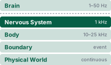
Physical AI stack focus for this chapter.
Why can a safety check miss its deadline even when it runs on its own processor core?
A correct refusal computed too late does not stop the motion it was meant to prevent. Separating a learned proposer from its permission path in software does not make the two independent while they still share memory, electrical power, clocks, or cooling. A burst of inference can then delay the check that should stop the machine, heat from the accelerator can slow the core that runs that check for seconds after the burst has ended, and a single supply or reset fault can silence both paths at once. None of these couplings appears on a software architecture diagram, and none shows up in average utilization, so a safety argument that has never been loaded on its real silicon rests on an untested premise. Moving the check to separate hardware removes some couplings and adds others, a communication delay and a longer chain of supplies and wiring, so no placement is independent by construction. Where each workload runs therefore decides whether the permission path can still refuse in time, and an action that crosses the causal boundary on a late refusal cannot be taken back.
Learning Objectives
- Conduct a dependent-failure inventory of the caches, memory controllers, interconnects, supply rails, clocks, resets, and thermal paths that each candidate placement leaves shared between the proposal and permission paths
- Explain why average bus utilization cannot bound a deadline, and identify which contention mechanism (bandwidth queueing, bank conflicts, or shared-cache miss handling) threatens a declared worst-case execution time
- Evaluate whether shared power and reset paths can defeat a selected permission placement
- Analyze thermal coupling and clock throttling hysteresis between multi-tenant workloads across disparate physical timescales
- Size a windowed watchdog’s service window from justified completion and inter-tick jitter bounds for a non-blocking record exchange
- Select among static reservation, spatial partitioning, workload reduction, and physical silicon relocation from measured interference and timing allowances, and allocate the dispatch-to-admission interval of an on-board or off-board proposer against the stopping budget
- Design an adversarial stress campaign whose falsification threshold is the permission path’s declared worst-case execution time (\(\PermissionTickWcet\))
- Construct a placement record formalizing the deployment envelope that scopes loaded observed maxima, thermal headroom, bus arbitration, mitigations, and untested conditions for release review
13.1 The Silicon Substrate
When the warehouse mobile manipulator’s permission check finishes late, its motor drives keep executing the last admitted command, and the loaded base covers distance that the stopping budget of Safety Enforcement never reserved. The control barrier filter, the stopping reservation, and the fallback ladder developed there hold only while the permission path completes its check inside its hard real-time deadline on every cycle. The enforcement record declares a worst-case execution time inside that deadline, a bound on the check running alone, and whether the bound survives while the learned proposers run beside it is a question about the silicon underneath. Workload placement decides which silicon executes each computation, and with that choice, which memories, interconnects, clocks, power supplies, and thermal paths each task shares with the others. In conventional computing, placement is an optimization over throughput, latency, or energy. On a machine whose refusals must arrive on time, it becomes a safety problem.
Modern silicon integration works directly against the separation the permission path needs. A contemporary heterogeneous system-on-chip (SoC) integrates general-purpose application cores, neural accelerators, real-time microcontrollers, and specialized safety islands onto a single monolithic die. On that die, these subsystems share memory controllers, dynamic random-access memory (DRAM) channels, system-level caches, on-chip network interconnects, voltage regulators, clock governors, and the physical package that carries away heat. While silicon integration lowers unit cost, board area, and inter-processor communication latency, it quietly couples through shared hardware the very execution paths that the software architecture keeps apart. The question placement must answer is whether the deterministic permission path can keep its deadline and its authority to refuse unsafe motion while the proposal path runs at full load on shared hardware. Answering it requires a bound on hardware interference for every shared physical resource, derived from worst-case timing analysis and validated under loaded stress tests.
On the warehouse mobile manipulator, the software architecture draws the proposal boundary between the Brain and the Nervous System as a clean logical boundary, and Part I adopted a working hypothesis about where that line falls in hardware, placing the permission path on a discrete safety microcontroller physically separate from the application SoC. The machine’s two physical jobs show what that separation must guard against. For the mobile base, whose mass-dominated mobility spends stopping clearance, an interconnect stall during visual feature extraction on the proposal engine could delay the permission path’s refusal while the loaded base approaches a rack end. Every tick of delay beyond the single cycle accounted for in the stopping budget is travel distance the machine never reserved. For the arm, whose contact-dominated manipulation spends force margin, a burst of neural accelerator traffic that evicts the permission path’s lookup tables from a shared cache could delay contact force validation while the gripper presses against a spring-latched cage door. The monolithic SoC is therefore an architecture the machine must be able to reject on evidence, and the discrete microcontroller is a design claim that must survive a loaded test rather than be assumed.
↩︎ The independence requirement on the permission path, and the two-processor split as a hypothesis that loaded tests must support, are established in The Independence Requirement and the Two-Processor Hypothesis.
Assigning the permission filter to a dedicated processor core does not create an isolated failure domain. A core running in isolation may still stall on memory arbitration, slow down under dynamic clock throttling, or suffer transient voltage drops when adjacent accelerators become active. Memory protection units and operating system process boundaries enforce spatial partitioning by preventing unauthorized reads and writes across address spaces. However, memory protection hardware governs access permissions rather than access timing. The underlying interconnect crossbar, memory controllers, and DRAM banks determine when memory transactions actually complete. Establishing a sound safety case requires both spatial partitioning to prevent memory corruption and temporal partitioning to guarantee bounded service times for shared hardware resources (Kopetz 2011; Rushby 1999).
Definition 13.1: Operational independence
Operational independence is the property that no activity, fault, or overload in the proposal domain can push the permission path’s execution past its deadline or disable its authority to refuse, through any resource the two paths share.
- Significance: It is the premise under which the stopping budget charges exactly one permission tick of detection delay. Every tick that proposal-side load adds beyond that one is travel at speed \(\SpeedAtDetection\) that the irreversibility test \(\StoppingDistance \le \ClearDistance\) never reserved, and a stall of unbounded length leaves the test with no bound at all.
- Distinction: Unlike spatial isolation, which private address spaces and separate cores supply, operational independence also covers time, supply, clock, reset, and heat. It is the placement-level form of what functional-safety standards call freedom from interference, the absence of cascading failures from one element into another of higher integrity (International Organization for Standardization 2018).
- Common pitfall: Arguing independence from the separation alone. A separate core, or even a separate chip, is the hypothesis the Nervous System adopted, not its proof; independence is argued one shared resource at a time, and a loaded test on the real silicon can refute the claim for any one of them.
Every placement claim must therefore name the physical and architectural resources that could delay or disable enforcement, alongside the mechanisms that bound their mutual interference. A shared die and a discrete safety microcontroller are competing hypotheses about those hardware dependencies, not interchangeable processor choices. Testing either hypothesis starts with what each path computes and the deadline it must meet.
13.2 Two Paths and the Resources They Share
When the neural chunk policy bursts at peak load on the same silicon that checks kinematic clearance, shared memory queues or thermal clock throttling can stall the refusal check past its sub-millisecond deadline while the mobile manipulator keeps moving. The third law, proposal is not permission, separates the two paths in authority; placement decides whether the hardware keeps them separate in time when the proposer is working hardest. The argument runs in three steps: it sizes what each path computes on the reference architecture from Part I, inventories the physical resources that could couple them, and scores four candidate placements against that inventory.
If a 40 ms neural proposer and a 400 μs-deadline safety loop share the same operating-system scheduler or memory controller, a single kernel preemption tail or memory-bus burst can stall the 1 kHz permission tick past its deadline. To prevent that stall, the mobile manipulator splits control across two execution paths with different systems requirements. The proposal path runs the chunk policy on the application processor at 20 Hz, ingesting synchronized navigation and wrist camera streams to emit coordinated base velocity and arm joint targets. Its 99th-percentile (p99) inference latency, vision processing included, consumes 40 ms (an illustrative benchmark; see the Reader Guide) of each 50 ms chunk period. Running in unprivileged user space, the proposal path holds no direct hardware authority over the motor drives. In the reference design from Part I, the permission path executes on a discrete safety microcontroller (MCU) at 1 kHz. On every tick, it checks the active trajectory and any candidate replacement against the stopping envelope from Stopping Envelopes, staging admitted setpoints into the outbound EtherCAT frame destined for the drives. This routine must finish within a chosen 400 μs deadline inside its 1 ms tick. It runs in a privileged real-time domain on a dual-core lockstep controller,1 whose cycle-by-cycle comparator flags divergent execution. That hardware guard is needed because a software envelope check cannot diagnose a silent fault in the CPU core executing it. Only the permission path holds memory-mapped input-output (MMIO) access to the fieldbus master carrying drive commands.
1 Dual-Core Lockstep: Dual-core lockstep runs identical instruction streams across two physical cores, typically offset by several cycles so that a single transient fault cannot corrupt both pipelines in the same way, while a hardware comparator flags any divergence. While lockstep execution catches internal CPU faults, it cannot catch bad envelopes computed from corrupted sensor inputs or common-mode voltage sags on shared power rails. Lockstep is therefore one piece of the safety microcontroller’s watchdog design rather than a complete integrity defense.
Definition 13.2: Heterogeneous silicon partitioning
Heterogeneous silicon partitioning is the architectural allocation of stochastic, high-capacity cognitive workloads (perception, learned policy evaluation) and deterministic safety loops (safety invariant checks, admission and fallback) across specialized execution domains isolated in hardware.
- Significance: Placing high-capacity neural deliberation and real-time safety enforcement on the same general-purpose operating system or compute engine creates common-mode failures. Kernel thread preemption, dynamic memory allocation, and time-slicing between accelerator contexts add tail delay that no measured average bounds, and a permission path exposed to that tail can miss its physical control deadline.
- Distinction: Unlike logical software process isolation (such as Linux containers or POSIX process priorities), silicon partitioning enforces isolation across independent hardware registers, tightly coupled memories (TCM), and dedicated peripheral buses.
- Common pitfall: Treating multicore CPU affinity as failure-domain separation. Cores on one die still share caches, memory controllers, clock trees, and power rails, the resources that operational independence (definition 13.1) must bound one by one.
These two processors run separate software stacks. Proposal inference, global scene-map updates, telemetry streaming, and fleet networking run on the application processor under Linux. While a real-time kernel patch shortens scheduler dispatch latency, it cannot bound latency tails added by unvetted device drivers, bus arbitration, or shared memory controllers.2 Similarly, zero-copy buffers reduce internal memory-bus traffic, but they do not remove contention at the physical memory controller.
2 PREEMPT_RT: The Linux real-time patch set makes most kernel code preemptible and runs interrupt handlers as schedulable threads, and it was merged into the mainline kernel in Linux 6.12 in 2024 after about two decades out of tree (KernelNewbies 2024). It shortens the scheduler’s latency tail but cannot bound delays that drivers, firmware, or shared memory add, so a PREEMPT_RT host needs a measured bound before it may carry any part of the permission tick.
KernelNewbies. 2024. Linux 6.12. Kernel release summary.
3 MPU and IOMMU: A memory protection unit (MPU) checks each CPU access against a few fixed address regions without translating addresses, so its cost is constant and analyzable. An input-output memory management unit (IOMMU) applies the same check to direct memory access (DMA) from accelerators and camera interfaces. Both govern where a memory transaction may access without arbitrating when the interconnect serves it; they enforce spatial partitioning while delegating deadline guarantees to hardware bus arbiters.
By contrast, enforcement and sensor validation run on the discrete safety microcontroller as bare-metal firmware governed by a hardware memory protection unit (MPU),3 with quadrature encoder counters, the inertial measurement unit (IMU) on its Serial Peripheral Interface (SPI) bus, and hardware timer capture channels mapped directly to dedicated physical pins. Each candidate proposal arrives from the application processor across a board-level serial link and is published into local memory via the seqlock mailbox of Lock-free and wait-free mailbox exchanges. No dynamic random-access memory (DRAM) is shared between the two paths. The memory protection unit isolates local state, while the dedicated peripheral bus insulates the enforcer’s execution path from the host’s memory traffic.
Admitting an entire plan is a different computation from running the cyclic permission tick. For example, the whole-plan validation routine of Action chunk horizons and reaction lag cannot run uninterrupted inside a 1 ms control loop without breaking timing guarantees. Instead, the runtime scheduler must preserve the real-time tick either by running admission as bounded, interruptible work or by moving it to a separate processor whose own timing is verified, and in either case admission ends with an atomic check of current state and sensor evidence right before activation. The running machine splits admission across these domains. The host performs the global geometry checks of Admission, Cyclic Checking, and Monitor Independence. The microcontroller checks the resulting record against bounded local evidence as background work below the tick’s priority, so the tick preempts it; section 13.6.2 lists the bounds that keep this background work from delaying the tick through the microcontroller’s own buses and memory. The resource budget must cover the active trajectory buffer, the resident fallback plan, the temporary admission workspace, and worst-case interruption overheads. The proposal generation rate also does not set the interval between successful admissions. Qualification must show that the end-to-end pipeline (transfer, admission, and activation) preserves the lease renewal bound, a guarantee the tick deadline alone cannot provide.
Similarly, the full volumetric scene map stays on the application processor. The permission path receives only a compact, bounded local evidence snapshot whose spatial coverage, state uncertainty, observation timestamp, expiration horizon, and transport integrity have been pre-validated for the proposed motion and its fallback maneuver. Updating the host map, serializing the snapshot, transporting it across the bus, validating admission, storing it locally, and running per-tick spatial queries are separate computational costs that need their own entries in the timing budget. A synchronous query to the host processor must never stall the permission tick. If a proposed trajectory strays outside the validated bounds or lifetime of the local snapshot, the MCU rejects it immediately. The microcontroller’s static memory budget must therefore show that the local snapshot buffer and resident fallback trajectories fit alongside the compiled enforcement binary.
Electrically, the power delivery network isolates the microcontroller, low-voltage drive logic, and electromechanical spring-brake coils onto a dedicated safety rail. This rail carries a local capacitive hold-up of 2 s and draws zero load from the proposal subsystem. Hardware qualification must verify that voltage transients from motor acceleration or neural accelerator bursts on the shared battery pack cannot trigger an undervoltage reset on this isolated rail. This local energy reserve keeps the logic alive and holds the mechanical brakes released throughout a controlled stop without supplying traction power. Achieving the powered deceleration profiles of The four rungs of the fallback ladder requires both an intact high-voltage drive path and a sink for regenerative braking energy. If either fails, the system must trigger a certified fail-safe fault response rather than relying on powered stopping-distance assumptions.
↩︎ The isolated permission rail and its hold-up sizing are established in Cross-budget coupling and permission rail isolation.
On an unloaded machine, the initial compute budgets look generous. Representative baseline costs on the safety microcontroller allocate 40 μs to sample motor encoders, read the IMU over SPI, and check the proposal’s evidence epoch; 80 μs to check kinematic and dynamic envelope constraints; and 15 μs to stage admitted setpoints into the outbound drive frame. That gives an unloaded enforcer execution time of 135 μs, or 54,000 cycles at the microcontroller’s 400 MHz clock. Measured against the 400 μs hard deadline, this baseline path leaves 265 μs of slack. Even the declared worst-case execution time (WCET) of 250 μs, the design envelope from Execution timing in the sub-millisecond loop, leaves 150 μs of headroom.
This timing margin cannot be spent entirely on shared-hardware contention. The response bound of equation 4.3 already charges the tick for blocking \(\TaskBlockingTime_i\) by lower-priority tasks (50 μs) and interference \(\TaskInterferenceTime_i\) from higher-priority tasks and interrupts (40 μs), both from the microcontroller’s own workload (Response time analysis and execution variance). Delay from hardware shared with the proposer is a separate cost because it lengthens the execution term \(\WorstCaseExecutionTime_i\) itself. A loaded tick meets its deadline only if its execution time, including all shared-hardware interference, stays below the deadline minus those internal overheads (90 μs), leaving an execution ceiling of 310 μs. Under the declared WCET bound, shared-hardware contention can add at most 60 μs of delay before the tick misses its deadline, and every placement analysis must account for this full budget.
The declared bound, not the deadline, is what a placement must defend. It bounds the tick’s execution in isolation, and the chosen placement claims that proposal-side load adds nothing to it. A loaded tick that runs longer than 250 μs therefore refutes that claim even when it finishes before the 400 μs deadline, because every margin downstream of the bound was computed on the premise it just broke. Each coupling in this chapter is priced against that falsification threshold, which section 13.7 formalizes and turns into a test campaign.
On the application processor, meanwhile, the neural policy’s 40 ms inference latency leaves 10 ms of margin within its 50 ms period. The enforcer’s sub-costs above are a baseline model rather than an integrated measurement, and local spatial-query overheads must also fit inside the cyclic budget. Full qualification requires measuring the loaded control cycle on the target to establish which spatial queries fall inside constraint evaluation and to account for any separate overheads; neither an unloaded benchmark nor an isolated query model can verify the declared WCET bound.
↩︎ The spatial-query workload the safety microcontroller must answer each tick is established in Volumetric metric maps and distance fields.
13.2.2 Four candidate placements against one shared-resource inventory
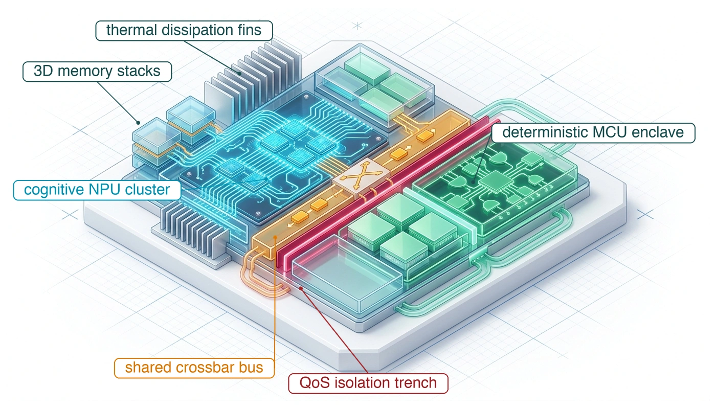
Choosing a hardware placement from a chip block diagram without checking every shared resource row, or without verifying that the commercial module exposes its on-die safety island to the integrator, leaves unpriced common-cause faults in the safety case. Four candidate placements for the permission loop span the options from sharing everything to sharing only the battery, and each is scored row by row against the shared-resource inventory (table 1). At the least isolated extreme, shared application cores (a) expose the permission loop to operating-system scheduling jitter, driver interrupt stalls, and kernel preemption tails, delays that can push execution past the 400 μs deadline and even the 1 ms control period. Moving to a real-time cluster in the host clock and power domain (b) dedicates execution cores to safety enforcement, yet it still shares the die’s cache hierarchy, memory controller, core supply rail, clock governor, and thermal path; section 13.3 prices its memory exposure, and section 13.4 shows the clock throttling that rules this candidate out.
To sever those host-domain couplings without leaving the package, modern automotive and industrial SoCs provide an on-die safety island (c). For instance, the Functional Safety Island of NVIDIA’s Orin-class SoCs integrates four dual-core lockstep Cortex-R52 processors, each with private tightly coupled memory, around 3 MB of on-island SRAM (NVIDIA 2023b). Because the island runs from an independent crystal oscillator and a dedicated voltage rail behind hardware firewalls that block unauthorized access from the rest of the die, the application governor cannot throttle its clock, and an enforcement routine whose code and data stay in island memory never waits on host DRAM arbitration. Even so, several couplings remain inside the package: shared substrate temperature, common reset and power sequencing logic, arbitration across the on-chip fabric carrying proposals or island DMA, and the common board-level power supply. Adopting an on-die island therefore requires reading back the configured firewall registers, tracing the power-sequencing logic, and running the loaded stress campaign of section 13.7 while the safety loop executes. Where those remaining die-level couplings cannot be bounded or the module does not expose the island, a discrete safety microcontroller (d) removes every on-die coupling altogether, trading silicon integration for an explicit board-level link from the application processor that section 13.6 budgets and characterizes.
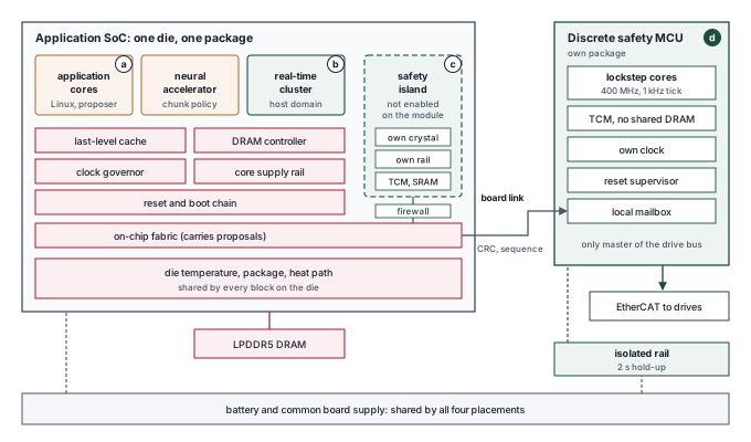
Laid out on the machine’s compute board, the four candidates differ in how many shared blocks stand between the permission tick and the proposer (figure 1). Candidates (a) and (b) sit behind the application die’s last-level cache, DRAM controller, clock governor, core rail, and fabric. The island (c) moves cores, crystal, and SRAM behind a firewall but stays in the same package and heat path. Only (d), a separate package clocked at 400 MHz with local TCM and a 2 s rail hold-up, leaves the die entirely and reaches it through a checked board link.
| Shared resource | (a) Shared cores | (b) RT cluster, host domain | (c) On-die safety island | (d) Discrete MCU |
|---|---|---|---|---|
| Cores and scheduler | Shared | Separated | Separated | Separated |
| Last-level cache and miss handling | Shared | Shared | Separated (private caches, TCM) | Separated (TCM) |
| DRAM controller and channels | Shared | Shared | Separated if the tick stays in island memory | Separated |
| On-chip fabric carrying proposals | Shared | Shared | Shared, behind a firewall | Replaced by a board link |
| Core supply rail | Shared | Shared | Separated (dedicated rail) | Separated (isolated rail) |
| Clock source and governor | Shared | Shared | Separated (dedicated crystal) | Separated |
| Reset and boot chain | Shared | Shared | Evidence needed | Separated if the supervisor is independent |
| Die temperature and package | Shared | Shared | Shared | Separated |
| Board supply and battery | Shared | Shared | Shared | Shared; evidence needed |
| Proposal transport | In-process memory | Shared-memory mailbox | Shared-memory mailbox through the firewall | Board link into a local mailbox |
On the inventory alone, candidate (c) is a strong contender. It separates the cache and miss handling, DRAM, core rail, and governed clock, the rows behind the strongest mechanisms the next two sections price, and leaves shared the die temperature, the fabric its proposals cross, the board supply, and a reset chain whose independence still needs evidence, each of which a qualification would have to cover. This verdict is provisional, since nothing has yet been priced, but the machine does not wait on it, because it adopts candidate (d) for a reason outside silicon capability. While the safety island exists on the physical SoC die, commercial edge modules packaging the application processor do not expose it to system integrators, reserving access for dedicated industrial platforms (table 2). Because an unexposed, unprogrammable safety island cannot serve as a valid deployment target, safety enforcement must move off the primary module.
| Platform (vendor statement date) | Safety island on the SoC | Available to the integrator | Source |
|---|---|---|---|
| Jetson AGX Orin module (2023) | Cortex-R52 island present | No | NVIDIA (2023a) |
| IGX Orin platform (2023) | Same island | Announced as offered | NVIDIA (2023a) |
| DRIVE AGX Orin (2023) | Island with dedicated crystal and rail, 3 MB SRAM | Yes, through DRIVE OS | NVIDIA (2023b) |
| Jetson Thor module (2026) | Not supported | No | NVIDIA (2026) |
| IGX Thor platform (2026) | Supported | Yes | NVIDIA (2026) |
NVIDIA. 2023a. Cortex-R52 and Cortex-R5 Cores in Jetson AGX Orin.
NVIDIA. 2023b. Functional Safety Island (FSI).
NVIDIA. 2026. Functional Safety Island in Jetson Thor T5000 Module.
Commercial platform exposure is therefore itself an architectural constraint. A vendor block diagram illustrating isolated silicon domains establishes what the hardware could theoretically execute, but system developers can use only the execution resources unlocked by board support packages and platform firmware. While specific commercial product tiers change over time, the engineering requirement to audit software accessibility before committing to a workload placement remains permanent.
The third law (principle 3) says a proposal is not permission, and that separation is empty if the proposal can delay the permission decision through hardware the two share. The four candidates differ in which resources they force the paths to share, and even for the discrete microcontroller the separation remains a hypothesis about timing under load that only a measurement of the loaded tick can support.
Choosing candidate (d) before pricing the shared die does not make the quantitative analysis of shared resources superfluous, for three reasons. First, each mechanism priced in section 13.3 and section 13.4 turns the rejection of candidates (a) and (b) from an architectural assumption into empirical evidence. Second, each mechanism names an obligation that the discrete design carries in miniature, because the microcontroller has its own DMA engines, interrupt controller, internal buses, and power supply, as detailed in section 13.6.2 and section 13.7. Finally, the same analysis provides the qualification blueprint for an integrator whose platform firmware exposes an on-die safety island. Unless a passage says otherwise, the calculations in section 13.3 and section 13.4 evaluate the permission tick placed hypothetically on the application die, using the sub-costs and timing budget assigned to the microcontroller. On a shared die, the first place proposal-side load encounters that tick is the memory system.
13.3 Contention for Shared Resources
Had the mobile manipulator placed its permission path on the application SoC, camera DMA, neural weight fetches, telemetry writes, cache writebacks, and enforcement reads would compete for memory service. Their simultaneous bursts determine the queue seen by the enforcer. On the selected machine, those host-side bursts delay the observation and chunk rather than the permission tick. The permission path encounters their effects as evidence age, refusing stale evidence and entering fallback if no admitted chunk renews the lease.
↩︎ How host-side memory contention, including camera DMA, ages observations is established in Ingestion Overhead and Memory Bus Contention.
13.3.1 DRAM bank conflicts, AXI4 burst slicing, and arbiter starvation
A small urgent read can wait behind a large transfer even when the memory bus is mostly idle over a longer interval. The deadline depends on the traffic already ahead of that read and on whether the controller lets it pass. This queueing delay, which arises when memory and DMA transactions share an interconnect and controller, is the mechanism inside the UMA crossbar trap, and its bound depends on transaction size, queue policy, and bank timing.
Each claimant’s average demand follows from its transfer size and event rate. On a shared multi-channel LPDDR5 interface, camera DMA streams, weight fetches at the policy rate, the enforcer’s reads, drive writes, cache writebacks, and logging together occupy a modest fraction of theoretical peak bandwidth on average. An engineer who inspects only that average concludes that most of the memory bus remains free. Memory crossbar arbiters and DRAM schedulers do not schedule average rates. They arbitrate discrete, bursty transactions, and two workloads with identical average throughput interfere with radically different latency profiles if one streams in small, sporadic packets while the other arrives in long, saturating blocks. The weight transfers that set the memory wall (Wulf and McKee 1995) of The memory wall are the long blocks here, and on a shared controller the proposer’s throughput limit becomes the permission path’s queue.
8 AXI4 (Advanced eXtensible Interface 4): Arm’s AMBA on-chip bus protocol permits incrementing bursts of up to 256 beats and forbids any burst from crossing a 4,096-byte address boundary. At a 16-byte beat, one full burst is exactly one such page, which is why the notebook below splits a weight tile into one transaction per page. An urgent read that waits for the granted burst to finish, as this example assumes, is a property of the chosen arbiter, not an AXI guarantee.
How long a safety read waits depends on transaction arbitration and DRAM scheduling. An accelerator moving weights in large 256 KB tiles generates discrete memory transactions across the internal system interconnect. The example assumes an arbiter that completes each granted burst before serving a different requester.8 Although bus protocols provide quality-of-service (QoS) priority signals (ARQOS), commodity memory controllers frequently treat these tags as advisory unless strict hardware priority bypass with bounded preemption latency is explicitly certified in register configurations. Whether an in-flight transfer can delay the urgent read, and whether queued tensor transactions can pass it, depends on the selected interconnect and arbiter. AXI burst limits alone do not establish a service-time or starvation bound.
Every memory request passes through four stages: the requester issues it, the interconnect arbiter grants it a slot, the memory controller queues it, and the target bank serves it. Each DRAM bank holds one open row in its row buffer. An LPDDR5 channel has 16 banks, divided into 4 bank groups at the higher data rates, or 8 larger banks, each formed by merging two, in an alternative mode (Steiner et al. 2022). A read to the open row (a row hit) needs only a column access. A read to a different row of the same bank (a row conflict) must first close the open row with a precharge (\(\RowPrechargeTime\)) and then open the new one with an activation (\(\RowActivationDelay\)). The memory standard sets a minimum time in nanoseconds for each step, 18 ns for both, and the controller can only wait whole cycles of its command clock. At the 6,400 MT/s data rate of the machine’s application SoC, that clock ticks every 1.25 ns, each step rounds up to 15 cycles, or 18.75 ns, and a conflict adds 37.5 ns (Luo et al. 2024). Bank-group spacing, refresh, and bus turnaround add further terms, which DRAM Contention and Interconnect Arbitration treats.
Steiner, Lukas, Matthias Jung, Michael Huonker, and Norbert Wehn. 2022. “Unveiling the Real Performance of LPDDR5 Memories.” Proceedings of the International Symposium on Memory Systems (MEMSYS), 1–3. https://doi.org/10.1145/3565053.3565062.
Luo, Haocong, Yahya Can Tuğrul, F. Nisa Bostancı, Ataberk Olgun, A. Giray Yağlıkçı, and Onur Mutlu. 2024. “Ramulator 2.0: A Modern, Modular, and Extensible DRAM Simulator.” IEEE Computer Architecture Letters 23 (1): 112–16. https://doi.org/10.1109/LCA.2023.3333759.
Rixner, Scott, William J. Dally, Ujval J. Kapasi, Peter Mattson, and John D. Owens. 2000. “Memory Access Scheduling.” International Symposium on Computer Architecture (ISCA), 128–38. https://doi.org/10.1145/339647.339668.
The controller also decides the order of service. Controllers that use first-ready, first-come-first-served (FR-FCFS) scheduling serve ready row hits before older requests that need a new row, which maximizes throughput (Rixner et al. 2000). A streaming accelerator supplies an unbroken run of row hits across its weight matrices, so an FR-FCFS scheduler can keep passing the safety core’s sporadic read until an internal starvation counter expires. Under a FIFO queue that lets no later arrival pass the safety read, the idealized wait is \[\MemoryBusQueueDelay = \sum_{k \in \QueuedTransactionSet} \frac{{\QueuedTransactionBytes}_{k}}{\text{BW}_{\text{peak}}} + \RowConflictCount (\RowPrechargeTime + \RowActivationDelay) \tag{1}\] where \(\QueuedTransactionSet\) holds the transactions ahead of the read, \({\QueuedTransactionBytes}_{k}\) is each one’s byte count, \(\RowConflictCount\) counts changes to a different row within an already active bank, and \(\text{BW}_{\text{peak}}\) is an optimistic service rate. Arbitration overhead and refresh add to the result. Exceeding the sensing allowance first violates the allocation to that subtask; it does not by itself imply that the whole tick misses its deadline. The worked comparison below keeps the sense allocation, declared execution bound, and physical deadline separate.
Napkin Math 13.1: The backlog budget
Problem: Suppose the same permission tick, with the same sub-costs and the same blocking and interference budget, ran on a core of the application SoC and read its sensor snapshot from the SoC’s shared DRAM. How much queued traffic could precede that read before the tick exceeds its sense allowance, its declared worst-case execution time, and its deadline?
Variables:
- Sense allowance 40 μs and 95 μs of constraint evaluation and drive-frame write (Illustrative sub-costs), declared worst-case execution time \(\PermissionTickWcet =\) 250 μs and deadline \(\EnforcerDeadline =\) 400 μs (Chosen), with 90 μs of blocking and interference charged as in equation 4.3 (Illustrative).
- Peak DRAM bandwidth \(\text{BW}_{\text{peak}} =\) 204 GB/s (Datasheet), served at that aggregate rate because the controller interleaves addresses across all channels (Illustrative premise).
- One backlog ahead of the read: a weight tile (64 transactions), a camera transfer, and a telemetry record, 88 transactions and 360,448 bytes, with 3 same-bank row conflicts (Illustrative), each costing \(\RowPrechargeTime + \RowActivationDelay =\) 37.5 ns (Datasheet). The snapshot itself is 4,096 bytes (Illustrative).
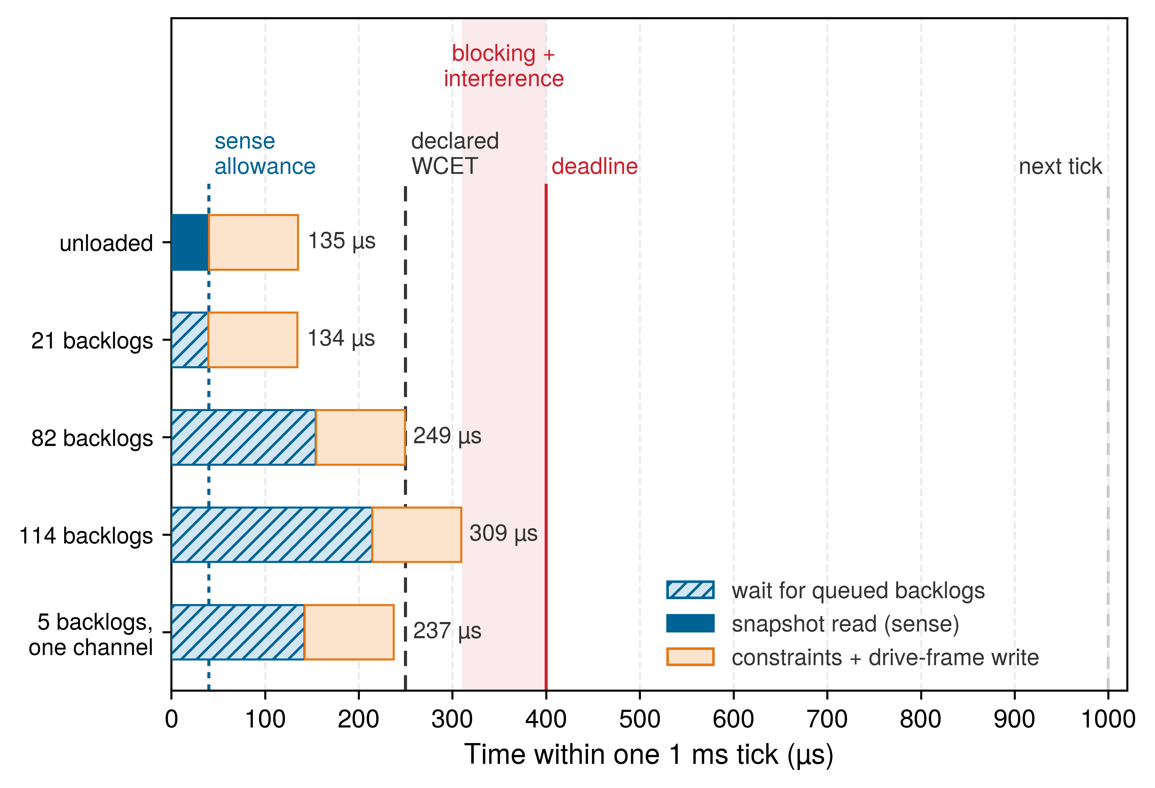
Math: By equation 1, one backlog waits 360,448 B \(/\) 204 GB/s \(+\) 3 \(\times\) 37.5 ns \(=\) 1.879 \(\MicroUnitPrefix\text{s}\), and the snapshot then reads in 0.020 \(\MicroUnitPrefix\text{s}\). The number of backlogs \(\AdmissibleBacklogCount\) that fit a read ceiling \(\ReadTimeCeiling\) is \(\lfloor (\ReadTimeCeiling - \SnapshotReadTime)/\MemoryBusQueueDelay \rfloor\). The sense allowance gives \(\lfloor (\) 40 \(-\) 0.020 \()/\) 1.879 \(\rfloor =\) 21. The declared bound leaves 155 μs for the read after the 95 μs of later work, so it is crossed beyond 82 backlogs; the deadline, less blocking and interference, leaves 310 μs for the tick and 215 μs for the read, and is crossed beyond 114. With validated priority bypass, only the one in-flight transaction waits ahead, and the read takes 0.04 \(\MicroUnitPrefix\text{s}\).
Result: Between 82 and 114 backlogs, the tick still meets its deadline but exceeds \(\PermissionTickWcet\). Within this stipulated FIFO model, the fixed isolated sub-costs remain unchanged, so the excess comes from shared-memory queueing. It refutes the placement’s timing premise even though this tick was on time. A measured overrun would instead require distinguishing an underestimated baseline from interference, as section 13.7 explains.
Systems insight: The read’s bound belongs to the memory controller, not to the workload. The bound exists only if the controller limits how much traffic it admits ahead of a safety read or lets that read bypass the queue, and an FR-FCFS controller serving a streaming accelerator provides neither unless its configuration is qualified to do so. At the SoC’s full bandwidth, though, plain queueing is a weak threat, since the allowance absorbs 21 backlogs. The interleaving premise carries much of that result. If the backlog and the snapshot shared one of the interface’s 16 channels, each backlog would take 28.4 \(\MicroUnitPrefix\text{s}\), the allowance would absorb 1, and more than 5 would cross the declared bound, so the address mapping belongs in the placement evidence. The mechanisms that actually threaten the declared bound are the ones this FIFO model omits, which section 13.3.2 prices next.
Drawn to scale on one 1 ms period, the thresholds show how far the declared bound sits from the deadline and the period (figure 2). The unloaded tick ends at 135 μs. The next three rows carry the largest backlog counts that keep each bound: 21 for the 40 μs sense allowance, 82 for the declared 250 μs, and 114 for the 400 μs deadline once 90 μs is reserved for blocking and interference. The bottom row confines the traffic to one memory channel, where 5 backlogs already reach the declared bound.
13.3.2 Which interference mechanism threatens the declared bound
The notebook’s arithmetic makes the shared die look safe, and that impression is the danger. The permission tick can absorb a stretch of its unloaded 135 μs cycle by a factor of 1.85 before it crosses the declared worst-case execution time, and by 2.30 before it crosses the deadline, once blocking and interference take their 90 μs. Bandwidth queueing at the SoC’s full rate does not come close. Two other mechanisms do, and both live in the shared cache rather than in DRAM.
A non-blocking cache tracks each outstanding miss in a miss status holding register (MSHR) and parks each dirty line it evicts in a writeback buffer until DRAM accepts it. Both structures are small and shared by every core behind the cache. When a streaming co-runner keeps them full, each miss of the victim core waits until an entry drains, so the victim’s delay grows with its own miss count times the aggressor’s drain time, not with the bytes it reads. Partitioning cache capacity does not help, because the partition divides the lines and leaves the MSHRs and the writeback buffer shared. Measured on commercial embedded multicores, MSHR contention raised a task’s worst-case execution time by up to 21× with the cache partitioned (Valsan et al. 2016), and a deliberate attack on the writeback buffer slowed a victim on a dedicated core by more than 300×, partitioned or not (Bechtel and Yun 2019). DRAM adds its own multiplier on top. An analytical bound for commercial controllers shows that each of the victim’s requests can wait behind every request that other cores may place ahead of it in the same bank, a number set by queue depth and the reordering window rather than by average bandwidth (Kim et al. 2014).
Kim, Hyoseung, Dionisio de Niz, Björn Andersson, Mark Klein, Onur Mutlu, and Ragunathan Rajkumar. 2014. “Bounding Memory Interference Delay in COTS-Based Multi-Core Systems.” IEEE Real-Time and Embedded Technology and Applications Symposium (RTAS), 145–54. https://doi.org/10.1109/RTAS.2014.6925998.
These slowdowns were measured on other platforms, on victims whose time was mostly memory stall, so they cannot be charged to the enforcer directly. Using them as assumed multipliers on its memory-stall share provides a sensitivity calculation, not a prediction of target behavior. If a fraction \(\CacheMissStallFraction\) of the unloaded tick waits on shared-cache misses and interference slows that fraction by a factor \(\InterferenceSlowdownFactor\) while the rest runs unchanged, the tick takes \(\UnloadedTickExecutionTime[(1-\CacheMissStallFraction) + \CacheMissStallFraction \InterferenceSlowdownFactor] = \UnloadedTickExecutionTime[1 + \CacheMissStallFraction(\InterferenceSlowdownFactor-1)]\). Setting that no larger than \(\PermissionTickWcet\) and solving for \(\CacheMissStallFraction\) shows that the loaded tick stays within the declared bound only while At the MSHR-class 21×, the declared bound falls once more than 4.3 percent of the tick is miss stall, and the deadline once more than 6.5 percent is. At the writeback-buffer attack’s 300×, the threshold is 0.28 percent. A target profile must establish whether the constraint evaluation exceeds those fractions; touching tables in shared memory alone does not establish its stall share. The mechanism that threatens the declared bound is therefore miss handling in the shared cache, amplified by bank queueing, and the only placements that remove it are those whose tick runs from private memory, candidates (c) and (d) of table 1. On (a) and (b), the measured stall share on the target and a regulation mechanism that bounds \(\InterferenceSlowdownFactor\) (section 13.6) are what a qualification must supply.
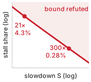
At a 21× slowdown, 4.3 percent miss stall breaks the bound.
13.3.3 Power-rail interference
When a neural accelerator steps its current draw in nanoseconds on a core supply rail shared with a permission core, the voltage droops across the package inductance and resistance before board regulators can respond, stretching logic gate delays or triggering adaptive clock stretching inside the permission tick. The rail at issue here is not the drive bus or the microcontroller’s isolated rail; it is the on-die core supply that a shared-die placement, candidate (a) or (b), would share with the accelerator inside one package. A sudden accelerator current step lowers the voltage available to every core on that supply, and the first-order package model is \[\CoreRailVoltageDroop = \PackageInductance \frac{d\ConductorCurrent}{d\TimeInstant} + \FiniteChange \ConductorCurrent \cdot \PackageResistance \tag{3}\] The placement decision depends on whether regulation, decoupling, and stored energy keep the permission path inside its characterized operating range. The package hierarchy and transistor-level delay model are developed in Inductive Voltage Droop and Gate Delay Stretch; here the model identifies the disturbance a shared core rail would carry into the permission tick. The chosen placement keeps its core supply out of that package, and its isolated rail must instead survive board-level events (drive-bus sag, a contactor trip, converter dropout), the disturbances of stress regime 1 and the transient generators of section 13.7.
For the illustrative package parameters, a 6 A step with a 2 ns rise through 30 pH gives 90 mV of inductive droop, and the same step through 8 m\(\OhmUnit\) gives 48 mV of resistive droop, 138 mV in all from a 0.850 V nominal rail. This pure \(\PackageInductance\,d\ConductorCurrent/d\TimeInstant\) term ignores on-die decoupling capacitance, and does not resolve the actual transient; power-integrity engineers instead design the delivery network to a target impedance9 across frequency, and the first droop is set by package inductance resonating with on-die capacitance. The alpha-power model10 (Sakurai and Newton 1990) relates the resulting voltage to gate delay: \[\frac{\GatePropagationDelay(\DroopedSupplyVoltage)}{\GatePropagationDelay(\NominalSupplyVoltage)} = \frac{\DroopedSupplyVoltage}{\NominalSupplyVoltage} \left( \frac{\NominalSupplyVoltage - \TransistorThresholdVoltage}{\DroopedSupplyVoltage - \TransistorThresholdVoltage} \right)^\VelocitySaturationExponent\] Here \(\TransistorThresholdVoltage\) is the modeled threshold voltage, stipulated as 0.420 V, and \(\VelocitySaturationExponent\) is the technology-dependent exponent, stipulated as 1.3. With those inputs, the modeled delay increases by 39 percent. This is a sensitivity calculation, not a measured reset threshold or a universal delay increase for every gate, and ignoring decoupling does not establish a guaranteed upper bound on a resonant transient. The stretch lasts nanoseconds, so it does not lengthen the tick by that percentage; it threatens the setup-time margin of the paths switching during the droop, and it grows without bound as the drooped voltage approaches \(\TransistorThresholdVoltage\). Many current processors detect the droop and stretch the clock until the rail recovers (Grenat et al. 2014), which turns a timing violation into lost cycles that the tick must absorb. Device characterization must establish whether the actual critical paths still meet setup time, how many cycles adaptive clocking removes, and whether undervoltage protection trips.
9 Target Impedance: Power-integrity engineers hold the delivery network’s impedance, seen from the die, below the allowed ripple divided by the largest current step, at every frequency the load can excite (Smith et al. 1999). A flat impedance bounds the droop from a current step of any shape, which a single \(\PackageInductance\,d\ConductorCurrent/d\TimeInstant\) term cannot. That documented bound is what a shared-die placement would owe the permission core’s rail, and what the discrete placement owes only its own isolated rail.
Smith, L. D., R. E. Anderson, D. W. Forehand, T. J. Pelc, and T. Roy. 1999. “Power Distribution System Design Methodology and Capacitor Selection for Modern CMOS Technology.” IEEE Transactions on Advanced Packaging 22 (3): 284–91. https://doi.org/10.1109/6040.784476.
10 Alpha-Power Law: The model was proposed in 1990 (Sakurai and Newton 1990) because short-channel transistors no longer followed the long-channel square law: carrier velocity saturates, and drain current grows as \((\SupplyVoltage-\TransistorThresholdVoltage)^\VelocitySaturationExponent\) with \(\VelocitySaturationExponent\) falling from 2 toward 1. Delay therefore depends on the headroom between supply and threshold, not on the supply alone. A low-voltage core chosen for efficiency has the least headroom, so it is also the most droop-sensitive home for the permission path.
Sakurai, Takayasu, and A. Richard Newton. 1990. “Alpha-Power Law MOSFET Model and Its Applications to CMOS Inverter Delay and Other Formulas.” IEEE Journal of Solid-State Circuits 25 (2): 584–94. https://doi.org/10.1109/4.52187.
Grenat, Aaron, Sanjay Pant, Ravinder Rachala, and Samuel Naffziger. 2014. “Adaptive Clocking System for Improved Power Efficiency in a 28nm X86-64 Microprocessor.” IEEE International Solid-State Circuits Conference (ISSCC), 106–7. https://doi.org/10.1109/ISSCC.2014.6757358.
Checkpoint 13.1: Which shared resource breaks the bound
Queueing, miss handling, and rail droop all delay the permission tick through hardware the two paths share. Before moving to heat, confirm that the distinctions among these physical mechanisms are clear:
A separate permission rail removes the modeled shared core-supply path, but the common battery, wiring, converter behavior, and return paths remain qualification obligations. Rail probes and independent timing instruments must observe them under simultaneous motor and proposal load. Droop and queueing both end within microseconds of the burst that causes them. The heat that the same accelerator dissipates does not, and it couples the paths on a timescale a million times longer.
13.4 Thermal and Timing Coupling
A permission core can suffer execution delays long after a heavy proposal workload has terminated, because thermal capacitance traps heat inside the package. While electrical droop and interconnect contention manifest over nanoseconds and microseconds, thermal coupling operates over seconds. When an accelerator and a real-time permission core share a silicon die, a cooling path, and an on-chip power management governor, sustained neural network inference can lower the clock frequency available to safety enforcement, and keep it lowered after the inference stops.
Thermal clock throttling is the automatic, hardware-enforced reduction of processor clock frequency triggered when sustained power dissipation pushes the silicon junction temperature (\(\JunctionTemperature\)) beyond a critical trip threshold (\(\ThrottleTripTemperature\)). On-die thermal sensing diodes alert the power management controller, which scales down clock frequency through hardware dividers or phase-locked loop (PLL) reconfiguration to prevent gate dielectric breakdown and thermal runaway. Because the physical die, package substrate, and heat spreader require time to dissipate this accumulated thermal energy, the reduced clock frequency persists long after the compute burst ends. For a co-located real-time task, this persistent slowdown can turn a nominal execution margin into a deadline overrun that lasts as long as the package takes to cool.
In this illustrative warehouse scenario, the robot’s electronics bay operates at an ambient temperature of 45\(\,^{\circ}\text{C}\). The thermal dissipation path follows the package row of figure 1, shared by every computational component on the application SoC die. The selected warehouse enclosure seals out airborne dust and conductive debris and uses conduction cooling rather than open fan vents. For a shared-die architecture in this enclosure, the conduction path must transfer all heat generated by sustained proposal inference to the chassis without driving the real-time permission core into a throttled clock state.
For a conduction-cooled enclosure, the total thermal resistance from junction to ambient (\(\JunctionAmbientThermalResistance\)) sums three distinct mechanical layers: \[\JunctionAmbientThermalResistance = \JunctionCaseThermalResistance + \InterfaceMaterialThermalResistance + \ChassisThermalResistance.\] Here, \(\JunctionCaseThermalResistance\) is the junction-to-case resistance of the silicon package, \(\InterfaceMaterialThermalResistance\) is the resistance through the thermal interface material, and \(\ChassisThermalResistance\) represents heat conduction through the metal enclosure to the ambient air. Over extended operation, mechanical shock and thermal cycling can degrade the interface material, increasing \(\InterfaceMaterialThermalResistance\). Simultaneously, battery discharge losses and motor drive electronics inject parasitic heat into the bay; battery Joule heating scales with the square of the discharge current (\(\ConductorCurrent^2 \ElectricalResistance\)). A robust thermal envelope must therefore account for both the mechanical cooling path and the peak concurrent actuator workload. A quiescent bench test on a cold board cannot replicate the thermal reality of a warm, multi-hour operating shift.
Consider an application SoC inside this bay modeled with a lumped junction-to-ambient thermal resistance \(\JunctionAmbientThermalResistance\) and a thermal time constant11 \(\PackageThermalTimeConstant\). Under a continuous power dissipation \(\DevicePower\), the silicon junction reaches a steady-state temperature of \(\AmbientTemperature + \DevicePower \JunctionAmbientThermalResistance\). When power steps to a new level, the junction temperature converges toward this new equilibrium along a first-order exponential trajectory governed by \(\PackageThermalTimeConstant\). This time constant represents the fast pole of the die and package thermal network. While heatsink and structural chassis poles operate on timescales of minutes to hours, holding the chassis at a constant baseline temperature provides an optimistic lower bound on junction heating.
11 Thermal RC Analogy: Heat flow is mathematically equivalent to electric current, temperature difference to voltage, thermal resistance (K/W) to electrical resistance, and heat capacity (J/K) to capacitance. Under a single dominant heat path, the silicon junction behaves as a first-order RC circuit with \(\PackageThermalTimeConstant = \JunctionAmbientThermalResistance \PackageThermalCapacitance\). The parameters in this scenario imply a lumped thermal capacitance of 4 J/K, representing the stored thermal energy the package must shed through \(\JunctionAmbientThermalResistance\) before the governor can restore the clock. Much like an electrical RC low-pass filter smooths voltage spikes, this physical thermal mass integrates fast fluctuations in proposal compute power into a slow, sustained temperature rise that directly governs the permission core’s clock.
Under the clock and thermal assumptions below, these dynamics eliminate the modeled configuration of candidate (b) in table 1. In that candidate design, the permission path runs on a real-time CPU cluster located on the main application SoC. Suppose this cluster shares the SoC’s primary clock and power management domain, sized so that the permission tick’s worst-case cycle count, run at the nominal clock, exactly meets its declared worst-case execution time. The sizing is not chosen to make the case fail. The declared bound is the worst execution the placement may assume, so judging the placement at that bound is the honest test, and a tick that executes at its bound has no slack against any slowing of the clock. When sustained neural network inference drives the junction temperature beyond the trip threshold \(\ThrottleTripTemperature\), the hardware governor halves the cluster’s clock frequency. As a consequence, every instruction cycle in the tick takes twice as long. The safety software executes the exact same code, but the shared governor injects an unmodeled cross-domain delay that isolated execution time profiling cannot detect. A discrete microcontroller, in contrast, runs on an independent oscillator and dedicated power rail beyond the reach of the SoC’s thermal governor. An on-die safety island fed by its own clock tree and voltage rail would likewise isolate clock generation from the governor, although it would still share the silicon substrate and require rigorous thermal qualification.
A throttled tick outlasts the workload burst because hardware governors enforce state-dependent hysteresis. To prevent the clock frequency from chattering rapidly around the trip line, the controller restores the nominal clock only after junction temperature drops below a lower clearance threshold \(\ThrottleClearTemperature\). Once proposal inference halts and chip power falls back to baseline, the junction relaxes toward its baseline equilibrium: \[\JunctionTemperature(\TimeInstant) = \QuiescentJunctionTemperature + (\ThrottleOnsetJunctionTemperature - \QuiescentJunctionTemperature) e^{-\TimeInstant/\PackageThermalTimeConstant} \tag{4}\] where \(\ThrottleOnsetJunctionTemperature\) is the junction temperature when throttling begins, \(\QuiescentJunctionTemperature\) is the baseline equilibrium under quiescent load, and \(\PackageThermalTimeConstant\) is the package thermal time constant. Solving equation 4 for the time required to cool from \(\ThrottleTripTemperature\) to \(\ThrottleClearTemperature\) gives \(\ThrottleRecoveryTime = \PackageThermalTimeConstant \ln[(\ThrottleOnsetJunctionTemperature - \QuiescentJunctionTemperature)/(\ThrottleClearTemperature - \QuiescentJunctionTemperature)]\), which fixes how long the hangover lasts in this scenario.
Napkin Math 13.2: The thermal hangover
Problem: Candidate (b)’s permission cluster shares the application die’s package and clock governor. Under continuous proposal inference, does the junction reach the trip threshold, what does the throttled clock do to the tick, and for how many ticks does the overrun persist after the load stops?
Variables:
- \(\AmbientTemperature =\) 45\(\,^{\circ}\text{C}\), \(\JunctionAmbientThermalResistance =\) 2 K/W, and \(\PackageThermalTimeConstant =\) 8 s (Illustrative; conduction-cooled bay).
- \(\QuiescentSocPower =\) 4 W for the permission loop with idle and memory power, and \(\InferenceLoadSocPower =\) 26 W with continuous proposal inference (Illustrative). The scenario holds this loaded power constant after throttling; a real device whose governor reduces power requires a coupled power-and-temperature model.
- \(\ThrottleTripTemperature =\) 95\(\,^{\circ}\text{C}\) and \(\ThrottleClearTemperature =\) 85\(\,^{\circ}\text{C}\) (Illustrative governor thresholds).
- \(\NominalClockFrequency =\) 1.2 GHz, halved to \(\ThrottledClockFrequency =\) 600 MHz (Illustrative); the tick is sized to \(\PermissionTickWcet =\) 250 μs at \(\NominalClockFrequency\) inside the 400 μs deadline and the 1 ms tick (Chosen), with 90 μs of blocking and interference charged as in equation 4.3 (Illustrative).
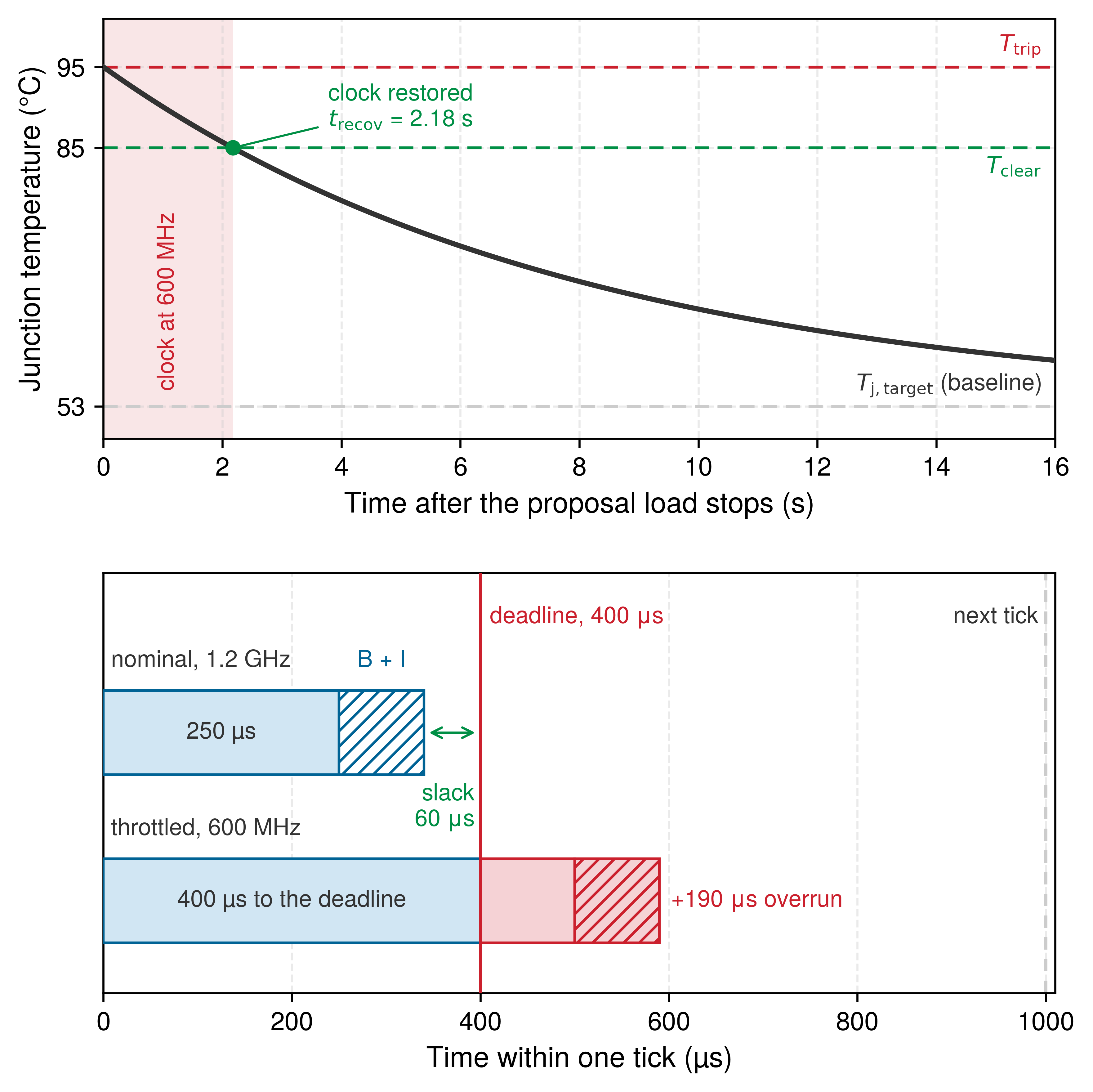
Math: The steady states are \(\QuiescentJunctionTemperature =\) 45 \(+\) 4 \(\times\) 2 \(=\) 53\(\,^{\circ}\text{C}\) and \(\LoadedJunctionTemperature =\) 45 \(+\) 26 \(\times\) 2 \(=\) 97\(\,^{\circ}\text{C}\), above the trip. Rising from the baseline, the junction trips after \(\PackageThermalTimeConstant \ln[(\LoadedJunctionTemperature - \QuiescentJunctionTemperature)/(\LoadedJunctionTemperature - \ThrottleTripTemperature)] =\) 8 \(\ln[(\) 97 \(-\) 53 \()/(\) 97 \(-\) 95 \()] =\) 24.7 s. The tick needs \(\TickCycleCount = \PermissionTickWcet \NominalClockFrequency =\) 300,000 cycles, which at 600 MHz take 500 μs. With blocking and interference the response grows from 340 μs to 590 μs, 190 μs past the deadline. By equation 4 the clock returns after \(\ThrottleRecoveryTime =\) 8 \(\ln[(\) 95 \(-\) 53 \()/(\) 85 \(-\) 53 \()] =\) 2.18 s, which spans 2,175 ticks of 1 ms.
Result: After about 24.7 s of continuous inference, every tick overruns its deadline by 47.5 percent for as long as inference continues, and for another 2.18 s after it stops.
Systems insight: While inference continues, the junction stays near \(\LoadedJunctionTemperature\), above the trip, so the cluster remains throttled for as long as the proposer runs, which is the worse case on a machine whose chunk policy runs continuously while it moves. The hangover adds the subtler one, in which pausing the proposer (at a stop, or when the policy idles) does not restore the clock for another 2.18 s, so a remedy that sheds proposal load cannot rescue the tick in time. Throughout, a refusal misses the drive frame timed to the deadline and waits for a later one. Because the throttled response still ends inside the period, each late refusal slips by about one tick, a distance the stopping budget can absorb (section 13.7). The case still disqualifies this modeled configuration, because the loaded tick has crossed the declared bound, every margin downstream was computed on the premise it breaks, and nothing in the premise limits a real governor to halving the clock. The lever is the heat path, not the tick’s code. Any \(\JunctionAmbientThermalResistance\) that keeps \(\InferenceLoadSocPower \JunctionAmbientThermalResistance\) below \(\ThrottleTripTemperature - \AmbientTemperature\) never trips, and an independently clocked placement is unaffected by that host governor. Its own thermal and clock limits remain separate qualification obligations.
The two timescales meet in one picture: a cooling curve measured in seconds holds the clock at 600 MHz, and every tick inside it, measured in microseconds, ends 190 μs past the deadline (figure 3). The scenario is also optimistic. Over a full shift, heat accumulating in the chassis raises the baseline \(\QuiescentJunctionTemperature\), which flattens the cooling gradient and lengthens recovery, and higher-order thermal poles in the enclosure can stretch the hysteresis by minutes. A shared-die placement would need a separately timed hardware fallback to stay safe across every exposed tick.
Heat completes the set of couplings, and placing it beside the other two shows how far apart they sit in time. The rail droop of section 13.3 acts within nanoseconds (\(10^{-9}\,\text{s}\)) of an accelerator current step, while thermal coupling develops over seconds (\(10^1\,\text{s}\)) as heat diffuses through silicon, package, and chassis. The separation is also a diagnostic: a latency spike that correlates with rail voltage points to power delivery network (PDN) impedance, and a slowdown that correlates with temperature points to the governor. Together with the tick they threaten, the couplings span about thirteen orders of magnitude on one machine, from nanoseconds to hours:
- \(10^{-9}\,\text{s}\) (Nanoseconds): Simultaneous tensor core switching generates \(\PackageInductance \cdot d\ConductorCurrent/d\TimeInstant\) inductive rail collapse, stretching transistor gate delays under the \(\VelocitySaturationExponent\)-power law within individual clock cycles.
- \(10^{-6}\,\text{s}\) (Microseconds): AXI4 crossbar arbitration and head-of-line FIFO queueing stall memory reads, as row-buffer precharge and activation penalties (\(\RowPrechargeTime + \RowActivationDelay\)) of tens of nanoseconds each accumulate across a queue.
- \(10^{-4}\text{--}10^{-3}\,\text{s}\) (Sub-milliseconds to milliseconds): The protected work itself. Sensor ingestion and the control barrier filter’s quadratic program run inside the permission tick, and fieldbus frames (such as EtherCAT) repeat on deterministic 1 ms cycles.
- \(10^0\text{--}10^1\,\text{s}\) (Seconds): Macroscopic silicon die and package heatsink thermal capacitance stores dissipated energy, enforcing governor throttling hysteresis (at least 2.18 s in this scenario) that degrades thousands of control ticks.
- \(10^2\text{--}10^4\,\text{s}\) (Minutes to hours): Structural chassis thermal mass and battery Joule heating accumulate heat, shifting bay ambient temperature \(\AmbientTemperature\) upward and eroding cooling headroom across a multi-hour shift.
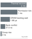
Coupling on one chassis spans nanoseconds to seconds.
Brooks, David, and Margaret Martonosi. 2001. “Dynamic Thermal Management for High-Performance Microprocessors.” IEEE International Symposium on High-Performance Computer Architecture (HPCA), 171–82. https://doi.org/10.1109/HPCA.2001.903261.
Because thermal mass and heat dissipation operate across seconds and hours, dynamic thermal management (DTM) (Brooks and Martonosi 2001) and reactive thread migration cannot restore a co-located permission loop before its next deadline expires. A safety-critical permission path requires guaranteed lower bounds on clock frequency and power supply integrity that survive sustained accelerator workloads. When a shared die cannot guarantee them, moving the permission engine onto an independently clocked and independently powered microcontroller removes the host-governor coupling, though the microcontroller must still stay within its own qualified supply, clock, and thermal limits under the common chassis conditions.
Checkpoint 13.2: Junction temperature and clock throttling
The cooldown and overrun in figure 3 follow from the stipulated thermal scenario, not from measured hardware behavior. Use them to check the consequences of the selected model:
13.5 The Boundary Contract
Relocating the permission path isolates the execution domains on separate processors, but the two still have to talk. Consider an upstream proposal writer, such as the chunk policy on the application processor, that stalls or crashes halfway through publishing an action chunk. The downstream safety enforcer running on the real-time microcontroller still owes the physical plant a deterministic actuation decision on its very next tick. Partitioning the compute engines isolates them only if the protocol lets the real-time reader inspect and reject an incomplete or in-flight record without ever waiting for the producer. The boundary contract therefore ties memory consistency directly to the deadline of the sensing and constraint-checking pipeline, and it is the one piece of the design that every placement, discrete or shared, must get right.
13.5.1 Immutable record mailboxes and non-blocking synchronization
Passing raw pointers into an application processor’s working buffer or coordinating across a blocking lock lets a slow or crashed planner expose the real-time reader to torn data structures, stale cache lines, or unbounded waits. To prevent those stalls, the boundary contract demands an immutable, self-contained record whose publication integrity the safety enforcer can verify in constant time. The proposal header and seqlock mechanism fix the message structure and publication rules, and workload placement adds the requirement to verify on the hardware that this channel meets its execution budget even when the interconnect is saturated.
Across heterogeneous silicon or separate physical chips, communication splits into two stages: link transport across the board and local publication inside the microcontroller’s memory domain. An ingress peripheral or DMA engine receives the payload over a physical link (SPI, PCIe, or Ethernet) and stages it into local memory. Where the target allows peripheral access to tightly coupled memory, this may be the mailbox directly; otherwise a bounded local copy publishes the received record into the mailbox. Link transport and local publication are therefore two separate timing obligations, and the boundary protocol governs only the second.
Inside that mailbox, the receive handler publishes fixed-size records with the single-attempt seqlock from the Nervous System, which discards a torn or in-flight record for this tick without a retry. Placement adds two obligations that the protocol alone does not discharge: memory attributes, barriers, and cache maintenance on the target must keep the local copy coherent, and the copy itself, at its largest payload, must fit inside the tick’s declared WCET.
↩︎ The single-attempt seqlock protocol, whose reader never spins or retries within a tick, is established in Lock-free and wait-free mailbox exchanges.
Memory consistency shows only that a proposal arrived without tearing, not that the command is safe to execute. Once the record passes sequence validation, the admission pipeline checks its algorithmic certificates, dynamic feasibility, transport integrity, and lease validity. Rejecting a corrupted or late proposal neither renews an expiring lease nor revokes an active, previously vetted command early. The actuator keeps executing the current plan while that plan’s lease, kinematic bounds, and state checks hold. If the current plan expires or the machine leaves its safe operating bounds, the microcontroller invokes the fallback ladder immediately. Host-side operating-system stalls, neural accelerator throttling, and asynchronous logging queues can never backpressure or delay this local decision.
Every cross-boundary exchange therefore carries two separately measured costs: board-level physical transport before publication, followed by a single bounded local read during the enforcement tick. Qualification test suites must record payload sizes, cache and memory settings, and worst-case rejection paths. Even a real-time enforcer that reads without blocking remains vulnerable if its own execution stalls, so software decoupling must be paired with independent hardware supervision of processor liveness.
13.5.2 Windowed watchdog timers and execution liveness
A standard countdown watchdog refreshed from a timer interrupt keeps getting fed after the control task has hung (Barr 2013), and a single late-only threshold cannot catch a corrupted program counter or a runaway phase-locked loop (PLL) clock that jumps into the watchdog service routine ahead of schedule. The single-attempt seqlock catches torn publication, and memory protection blocks cross-domain writes, but neither verifies that the safety enforcer software is alive and running its checks at the intended rate. The Nervous System feeds the microcontroller’s self-watchdog only when a tick finishes all of its checks, which catches a late or missing feed. On shared or heterogeneous silicon, the enforcer can fail in either direction: bus contention and memory starvation can stall its progress, while PLL clock glitches or control-flow corruption can make instructions run too early. Protecting the plant therefore requires a two-sided bound on watchdog servicing.
Barr, Michael. 2013. Bookout v. Toyota Motor Corp.: 2005 Camry L4 Software Analysis.
↩︎ The supervisory timers, from the chunk lease to the self-watchdog timeout, are established in Supervisory timers and proposal wire contracts.
High-integrity physical AI systems enforce this discipline with windowed watchdog timers. Unlike standard countdown timers that catch only late feeds, a windowed watchdog enforces both a lower threshold (the closed window, \(\WatchdogEarliestServiceTime\)) and an upper threshold (the open window, \(\WatchdogLatestServiceTime\)), rejecting any refresh that arrives too early or too late:
- Early-kick violation (\(\WatchdogServiceTime < \WatchdogEarliestServiceTime\)): If software refreshes the watchdog before the lower threshold has elapsed, the hardware watchdog controller flags an immediate fault and trips the emergency safe state. An early refresh signals disrupted control flow: a corrupted program counter may have skipped safety barrier checks to branch straight into the housekeeping routine, a stack overflow may have aborted intermediate kinematic checks, or a PLL multiplier glitch may have sped up the clock. Because a compromised execution path could still happen to feed the timer inside the valid window, primary hardware monitors (independent clock monitors and rail supervisors with isolated voltage references) must catch PLL runaways and supply dips first, leaving the windowed watchdog as a backstop.
- Late-kick violation (\(\WatchdogServiceTime > \WatchdogLatestServiceTime\)): If the timer counts past \(\WatchdogLatestServiceTime\) without a valid refresh from the enforcer, the counter underflows and asserts an unmaskable hardware reset line. A late kick shows that the safety enforcer stalled, whether starved of bus cycles by neural accelerator traffic on a shared crossbar, deadlocked in an unhandled exception handler, or delayed by cache evictions.
- Valid service window (\(\WatchdogEarliestServiceTime \le \WatchdogServiceTime \le \WatchdogLatestServiceTime\)): A refresh inside this interval confirms only that the service call arrived on time. It does not prove that the software ran every required check in the dispatch loop. Full diagnostic coverage combines windowed timing with challenge-response checks or independent hardware supervision.
If the controller feeds once after each successful tick, the watchdog measures the interval between feeds. Let completion offset \(\CompletionOffset_n\) from tick \(\TickIndex\) start lie in \([\MinimumCompletionOffset,\MaximumCompletionOffset]\), and let \(\TickPeriodJitterBound\) bound the deviation of the interval between consecutive tick starts from \(\NominalTickPeriod\). A conservative range for the inter-feed interval is given by equation 5: \[\InterFeedInterval\in[\NominalTickPeriod-(\MaximumCompletionOffset-\MinimumCompletionOffset)-\TickPeriodJitterBound,\;\NominalTickPeriod+(\MaximumCompletionOffset-\MinimumCompletionOffset)+\TickPeriodJitterBound] \tag{5}\] This formulation captures the two extreme consecutive tick completions:
- Shortest interval (late-to-early compression): Tick \(\TickIndex\) finishes as late as possible (\(\MaximumCompletionOffset\)), and Tick \(\TickIndex+1\) finishes as early as possible (\(\MinimumCompletionOffset\)); the elapsed time between consecutive feeds is compressed to \(\NominalTickPeriod - (\MaximumCompletionOffset - \MinimumCompletionOffset) - \TickPeriodJitterBound\).
- Longest interval (early-to-late expansion): Tick \(\TickIndex\) finishes as early as possible (\(\MinimumCompletionOffset\)), and Tick \(\TickIndex+1\) finishes as late as possible (\(\MaximumCompletionOffset\)); the elapsed time between consecutive feeds expands to \(\NominalTickPeriod + (\MaximumCompletionOffset - \MinimumCompletionOffset) + \TickPeriodJitterBound\).
Engineers set \(\WatchdogEarliestServiceTime\) and \(\WatchdogLatestServiceTime\) around this range once timing analysis and test evidence justify its bounds, while keeping the late-trip threshold inside the plant’s fault budget. A single tick’s nominal execution time is not enough to set a watchdog window. On the running machine, \(\NominalTickPeriod\) is the 1 ms tick, and the declared worst-case execution time of 250 μs gives the execution contribution to \(\MaximumCompletionOffset\). The completion offset must also include the internal blocking and interference charged to the tick, so both offset bounds must use the same tick-start reference. Conversely, the nominal unloaded measurement of 135 μs cannot serve as \(\MinimumCompletionOffset\); early-exit paths, short branches, or trivial constraint checks can finish much faster than nominal paths. The shortest tick-start-to-completion interval observed during a stress and fault-injection campaign gives evidence for \(\MinimumCompletionOffset\), and a justified lower bound must also cover healthy paths the campaign did not exercise. Similarly, measured cycle-to-cycle period jitter under peak bus contention supports the bound \(\TickPeriodJitterBound\), with allowances for unobserved conditions, rather than an idealized absolute phase offset. If a team has only absolute phase bounds, it must take the maximum difference between consecutive phase offsets before using this expression.
The two ends of the window are set by different arguments. The lower end of equation 5 sets \(\WatchdogEarliestServiceTime\). Once \(\MinimumCompletionOffset\) and \(\TickPeriodJitterBound\) have justified bounds, supported by a campaign and allowances for unobserved healthy paths, any feed earlier than the resulting lower bound lies outside the qualified healthy range, and the machine’s self-watchdog, which has only a late trip, gains the early trip it lacks. The upper end is not used as \(\WatchdogLatestServiceTime\). It marks the latest a healthy tick can feed, so \(\WatchdogLatestServiceTime\) must sit at or beyond it, and how far beyond is a separate choice of fault-detection latency, judged against what the plant can tolerate while a dead enforcer goes undetected. The machine keeps the selected 5 ms timeout, several ticks beyond the window, so that transient delays do not trigger spurious resets; problem 5 converts that timeout into base travel. The late trip also answers a different question from the falsification threshold. A tick that runs past the declared WCET but still feeds within the window refutes the placement’s timing premise, and the loaded campaign, not the watchdog, must catch it; the watchdog’s upper end catches only an enforcer that has stopped feeding altogether.
Setting a multi-tick timeout is an engineered fault-detection latency, not proof that missing several control cycles is harmless. If the microcontroller crashes or resets, it cannot run MCU-controlled powered deceleration. A drive-autonomous SS1 remains available only if its independent trigger, drive controller, supply, and drive-energy and regenerative-sink paths survive the fault and are qualified for that response. Otherwise, the platform falls back to its separately qualified passive braking, friction deceleration, or hardwired mechanical interlocks. Total fault-handling latency (watchdog trip delay, supervisory reset propagation, and brake engagement) must therefore fit inside the plant’s certified safety-stop budget. Engineers cannot justify a slow watchdog timeout by citing powered braking distances when the fault being detected disables the processor that commands those brakes.
To catch control-flow corruption where a broken loop still passes through the watchdog service call inside the valid time window, high-integrity designs add challenge-response checkpointing. An external hardware supervisor or isolated safety coprocessor sends pseudo-random seeds to the enforcer at runtime. Instead of writing a fixed value to a register, the enforcer must return a signature computed from fresh sensor frame hashes, constraint-barrier checks, and intermediate trajectory stages. Diagnostic coverage depends on whether a corrupted execution path can replay or compute a valid signature by chance. If the enforcer fails the challenge or misses the window, the external supervisor asserts a hardware torque-inhibit line (such as Safe Torque Off on an electric drive). Direct torque removal stops actuators from driving into hazards, but it is not a controlled powered stop; the resulting passive coast-down or mechanical braking profile needs its own qualification and safety-case evidence.
Both the boundary contract and its hardware supervision apply to every workload placement. Whether the learned policy and the real-time safety enforcer sit on separate boards, separate chiplets, or partitioned cores on one SoC, the design must pass records without blocking and verify liveness in hardware. What changes from one placement to another is how much cross-domain interference the tick must absorb, and every mechanism that bounds that interference carries its own price in silicon area, bus bandwidth, and board complexity.
13.6 Silicon Isolation Decisions
Suppose a loaded test catches one of these couplings, a tick that exceeds the declared bound under proposal load. The team then has four remedies, each paid for in a different currency: static reservation, spatial partitioning, workload reduction, and physical relocation to separate silicon (table 3). The machine’s own choice, relocation, is the last of them, and it carries a transport budget that the section closes by allocating. The table maps the four remedies, the paragraphs after it develop the mechanisms it names (bandwidth regulation, cache coloring, bank partitioning, and the rest), and its last column states when one remedy is no longer enough and the design must escalate to the next.
| Remediation Strategy | Target Coupling Layer | Implementation Mechanism | Systems Engineering Trade-Off | Residual Vulnerability | When to Escalate |
|---|---|---|---|---|---|
| Static Reservation | CPU execution time, OS scheduling preemption | Fixed-priority scheduling, ARINC 653 time slots, per-core memory-bandwidth regulation (MemGuard) | Capacity withheld from other work, including during quiescent states | Micro-architectural contention beneath OS visibility (shared L3, DRAM bank conflicts) | Memory bus or cache stalls violate real-time deadlines despite \(100\%\) CPU core allocation |
| Spatial Partitioning | Cache capacity thrashing, DRAM bus contention | Cache coloring or way partitioning, DRAM bank partitioning (PALLOC), Arm MPAM, MPU/IOMMU domains | Structural fragmentation; smaller perception working set may increase off-chip traffic | Unpartitionable DRAM controller queues, row-buffer locality reordering, PDN voltage droop | Measured rail disturbances violate characterized limits, or DRAM queue stalls exceed the bound |
| Workload Reduction | Memory throughput saturation, peak thermal power | Model quantization (INT8/FP8), context downsampling, halved policy rate | Degraded policy tracking fidelity; increased control phase lag near dynamic stability boundaries | Common clock distribution trees, shared Power Management Units (PMU), unified reset domains | Model accuracy drops below operational limits, or shared clock/reset faults propagate across domains |
| Physical Relocation | Shared power, clock, reset, or unbounded controller interference | Separate enforcer MCU with independently assessed power, clock, memory, and sensor/actuator path | More board area and an external communication budget | Harness, transceiver, and common-supply faults remain | Choose when the shared die cannot provide evidence for required timing and fault containment |
13.6.2 The board-link budget and the dispatch-to-admission interval
Moving the enforcer onto a discrete microcontroller removes on-die contention only to introduce a board-level serial hop and a split validation pipeline whose elapsed time ages sensor observations while the base keeps rolling down the aisle. That elapsed time closes the interval left unallocated in The latency waterfall: the span from perception dispatching an observation frame to the safety enforcer admitting the resulting action chunk, called the dispatch-to-admission interval \(\DispatchAdmissionInterval\) (the second row of The capture-to-brake-onset timing budget of the running machine). It covers the remaining proposer inference after dispatch, serialization across the board link, frame receipt and deserialization on the microcontroller, host geometry checks and bounded local admission checking, trajectory buffer activation, and the wait for the next permission tick. Because the stopping budget starts at sensor capture, every millisecond of \(\DispatchAdmissionInterval\) is base travel on aging evidence, paid for out of the stopping budget’s spare clearance.
↩︎ The composite stopping budget, which leaves the dispatch-to-admission interval out of the pre-brake delay and pays for it from the remaining clearance, is established in Sizing the composite stopping budget.
Napkin Math 13.3: The board-link toll
Problem: The machine’s permission path runs on a discrete microcontroller that receives each chunk over a board link. How long may the interval from perception dispatch to admission last before the finished stopping budget has nothing left at the aisle speed?
Variables:
- Chunk policy p99 inference 40 ms (Illustrative), charged in full after dispatch, which is conservative because its vision stage already lies in the dispatch age of The latency waterfall.
- Serialized chunk \(\SerializedChunkVolume =\) 4,096 bytes on a \(\SerialLinkClockFrequency =\) 25 MHz SPI link (Illustrative).
- Deserialization 2 ms, aggregate trajectory validation 18 ms, and activation 1 ms (Illustrative allowances), and up to one 1 ms permission tick of waiting (Chosen).
- At \(\SpeedAtDetection =\) 1.3 m/s the finished budget leaves \(\SpareStoppingClearance =\) 131.0 mm (Derived).
The validation allowance covers both the host geometry check and the MCU’s bounded local admission check, including their scheduling delays. The example does not allocate a separate duration to each. Their combined elapsed contribution must fit this allowance; qualification cannot omit host validation or count the entire allowance again on the MCU.
Math: Serialization takes \(8\,\SerializedChunkVolume/\SerialLinkClockFrequency =\) 1.31 ms. The allocation totals \(\DispatchAdmissionInterval =\) 40 ms \(+\) 1.31 ms \(+\) 2 ms \(+\) 18 ms \(+\) 1 ms \(+\) 1 ms \(=\) 63.3 ms, which the base covers as 82.3 mm of travel. The spare pays for at most \(\DispatchAdmissionCeiling = \SpareStoppingClearance/\SpeedAtDetection =\) 131.0 mm \(/\) 1.3 m/s \(=\) 100.8 ms, so the allocation leaves 37.5 ms, or 48.7 mm of positive reserve. Doubling the chunk or halving the link clock adds only another 1.31 ms; adding one more inference’s worth of delay, 103.3 ms in all, exhausts the spare.
Systems insight: The board link that buys silicon separation costs about one millisecond, a small fraction of \(\DispatchAdmissionInterval\); proposer inference and aggregate trajectory validation dominate the interval. The stipulated discrete-placement allocation therefore fits the stopping budget, whereas a slower policy or a heavier validation kernel could exhaust it. The allocation is a target that qualification must confirm, not a relaxed runtime margin. The deterministic portion of \(\DispatchAdmissionInterval\) ages observation evidence and is charged here, while runtime variance between renewals drains the 5 ms renewal-jitter budget, which host-side memory contention alone can saturate.
With \(\DispatchAdmissionInterval\) formally allocated, the event timing table (The capture-to-brake-onset timing budget of the running machine) contains no undefined intervals. Total plan replacement latency from sensor capture to chunk admission (equation 11.3) is 114.9 ms, while total elapsed time from capture to emergency brake onset in the event of an unresponsive proposer is 196.9 ms. Both figures represent budget allocations that the loaded stress-testing campaign in section 13.7 must validate using physical hardware trace timestamps.
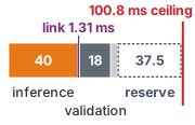
The board link costs 1.31 ms of a 63.3 ms allocation under a 100.8 ms ceiling.
Allocating the interval also exposes interference that the discrete placement keeps inside the microcontroller. The link’s receive DMA engine and its completion interrupt, the fieldbus master dispatching motor drive frames, background local admission checking, and the periodic ingestion of evidence snapshots all contend for the microcontroller’s internal crossbar, interrupt controller, and memory banks. Every potential interference path demands an enforceable bound: assigning SPI and fieldbus interrupt priorities strictly below the deterministic permission tick, allocating dedicated DMA channels, and mapping safety state to independent tightly coupled memory banks. The loaded validation campaign in section 13.7 must saturate the communication link and execute maximum-length plan validation while simultaneously triggering the refusal branch. Classical response-time analysis for the periodic tick, with its higher-priority preemption and lower-priority blocking terms, provides the formal static counterpart to those empirical stress tests.
↪ Response-time analysis for a periodic tick, with its preemption and blocking terms, is developed in Real-Time Timers, Watchdogs, and Schedulability.
These remediation pathways determine which computing resources engineers must statically reserve or physically isolate. Two subsequent architectural decisions govern the remaining placement budget: whether any portion of proposal generation may be offloaded across an external network, and which candidate accelerator silicon completes autonomous missions within the chassis energy reserve. Off-board compute is first a timing question, and it comes first because energy efficiency matters only among architectures that already meet their deadlines.
13.6.3 Off-board compute and mission energy
Querying a remote data center over factory Wi-Fi or private 5G subjects an offloaded policy to radio multipath fading, base-station handoffs, and packet retransmissions, yet the returned trajectory must still arrive inside the local 55 ms lease-renewal window. Off-board computation operates under the exact same timing windows as a local board interconnect, so an offloaded result must fit the target admission window before it can be considered for admission: \[\OffloadTailNetworkTime + \OffloadTailProcessingTime \le \OffloadTransactionWindow, \tag{6}\] where \(\OffloadTransactionWindow\) is the allocation for the network-and-remote-processing interval of a particular transaction. The complete dispatch-to-admission interval must also charge host validation, local deserialization and admission, activation, and tick waiting against the 100.8 ms ceiling (notebook 13.3). A continuing pipeline must satisfy that evidence-age ceiling and the accepted-result gap required for lease renewal. The lease less renewal jitter (55 ms on the running machine) directly limits transaction latency only under a serial, non-overlapping convention; with overlapping requests, stage capacity and actual inter-admission gaps require separate checks. Qualification must measure the complete end-to-end tail at the required reliability level and retain the same evidence, state, and lease checks as local admission.
Empirical robotics deployments demonstrate how severely this constraint restricts offloading. In RT-2, large vision-language-action (VLA) models ran in a multi-TPU data center queried over wireless networks; under real network conditions, the 55-billion-parameter model executed at only 1 to 3 Hz, while the 5-billion-parameter model reached approximately 5 Hz (Brohan et al. 2023). Wireless links in industrial deployments (whether Wi-Fi or private 5G) introduce severe latency tails from radio-frequency multipath fading, base-station handoffs, and packet retransmissions. At 5 Hz, a fresh plan arrives only once every 200 ms, 3.6 times the renewal window, while the 55-billion-parameter model delivers outputs at best every 333.3 ms. Neither remote pipeline could sustain lease renewal on this machine. Because the published study documents overall throughput frequencies rather than an explicit breakdown between network latency and remote execution phases, one cannot determine whether a lower-latency wireless link could close the gap; qualifying any remote lease-renewal pipeline requires profiling the full tail distributions of both components. Instead, large remote foundation models are best positioned to synthesize coarse semantic goals or task decompositions, leaving high-frequency action chunk generation to an onboard policy. Coarser planning workloads operating on second-scale horizons are better candidates for edge offloading. FogROS2, for example, offloads ROS 2 compute graphs to cloud and fog instances, reducing grasp-planning latency from 14 s on local edge silicon to 1.2 s (Ichnowski et al. 2023). That acceleration speeds macro-task completion while leaving high-frequency microcontroller execution untouched. Packet loss or complete link disconnection must leave the onboard enforcer and its certified safe-stop routine fully operational. Neither remote offloading nor offline compilation eliminates the obligation to guarantee timely execution on local silicon.
Brohan, Anthony, Noah Brown, Justice Carbajal, Yevgen Chebotar, Xi Chen, Krzysztof Choromanski, Tianli Ding, et al. 2023. “RT-2: Vision-Language-Action Models Transfer Web Knowledge to Robotic Control.” arXiv Preprint arXiv:2307.15818.
Ichnowski, Jeffrey, Kaiyuan Chen, Karthik Dharmarajan, Simeon Adebola, Michael Danielczuk, Víctor Mayoral-Vilches, Nikhil Jha, et al. 2023. “FogROS2: An Adaptive Platform for Cloud and Fog Robotics Using ROS 2.” IEEE International Conference on Robotics and Automation (ICRA), 5493–500. https://doi.org/10.1109/ICRA48891.2023.10161307.
Placement also decides which accelerator hosts the proposal path, and that choice reaches the permission path through energy as well as time. The chip’s power is the load term that set the junction temperature in section 13.4, and it draws on the same battery whose sag the isolated rail must ride through. Among architectures that satisfy these timing bounds, candidate silicon must also complete the physical mission within the chassis energy reserve. Energy optimization often presents a subtle engineering trade-off. A lower-power edge accelerator draws fewer watts during active inference, yet if it extends execution latency, peripheral loads (lidar, depth cameras, cooling fans, and motor holding currents) remain energized longer. Conversely, a higher-throughput neural accelerator reduces mission energy only as long as faster compute actively shortens overall task duration. Once physical manipulator kinematics or vehicle velocity limits dominate the execution timeline, accelerating compute further merely burns excess power without saving task time, driving up total energy consumed per completed cycle.
For an assigned physical workload with steady-state compute power and baseline chassis power draw, total mission energy follows the relation: \[\MissionEnergy = (\ComputeChipPower + \StaticChassisPower) \times \MissionDuration\] Evaluating this expression requires an empirical or rigorously modeled mission duration \(\MissionDuration\) for each candidate silicon configuration. Transient motor acceleration spikes, DC-DC converter losses, task retries, and quiescent dwell intervals demand explicit energy accounting whenever they diverge across platforms. Systems engineers cannot rank candidate SoCs simply by comparing datasheet figures such as peak tera-operations per second (TOPS) or nominal thermal design power (TDP). The workload to measure is the machine’s own proposal pipeline, from camera ingestion through the chunk policy, and final silicon placement requires evaluating the compiled neural graph, its memory footprint, and the thermal assembly as one system. This chapter does not rank accelerators for the running machine, whose record carries no measured mission duration for any candidate; the relation states what such a ranking must measure. With reserved memory bandwidth, board-level transport latency, and battery energy draw accounted for in the allocation model, the next step is experimental verification: testing on the physical hardware whether these isolation choices keep the permission tick within its bound and preserve braking response under worst-case concurrent load.
13.7 Empirical Verification of Silicon Isolation
The thermal hangover refuted candidate (b) from a model, but a placement that survives every model still has to face a measurement that could refute it. A claim of silicon isolation between an unverified learned workload and a safety enforcer must therefore reduce to a testable bound on enforcement latency and refusal availability. This bound must hold across all declared proposal workloads, junction temperatures, and operational modes. If shared-resource contention delays an enforcer refusal past its physical deadline, the claimed operational separation has failed, whatever architectural isolation was promised on paper.
13.7.1 The worst-case execution time falsification threshold
When a loaded permission tick runs for 260 µs against a declared isolated worst-case execution time of 250 μs, it finishes well inside the 400 μs deadline yet still refutes the claim that shared hardware added zero interference. The budget section of section 13.2 introduced the permission tick’s declared worst-case execution time (\(\PermissionTickWcet\)) as this falsification threshold, and a test designed to refute a placement must name the exact measured quantity it compares against that bound. In this example, the declared worst-case execution time bounds the task in isolation, whereas a qualified execution model can instead include bounded resource interference. Here, microarchitectural interference from hardware shared with co-running workloads lengthens the execution term rather than appearing as a separate term of the response-time bound (equation 4.3); the loaded \(\WorstCaseExecutionTime_i\) includes that penalty, beside the blocking \(\TaskBlockingTime_i\) and interference \(\TaskInterferenceTime_i\) that the microcontroller’s own tasks contribute.
The pass-fail threshold for silicon isolation derives directly from the system specification. The machine’s permission path specifies a declared worst-case execution time \(\PermissionTickWcet =\) 250 μs, representing the isolated execution parameter \(\WorstCaseExecutionTime_i\) in equation 4.3. It must complete each permission evaluation within a chosen enforcer deadline \(\EnforcerDeadline =\) 400 μs, which is nested inside the overall permission period \(\PermissionLoopPeriod =\) 1 ms. When measured under operational load, total enforcer execution time is the sum of isolated execution latency and cross-workload hardware interference, as formalized in equation 7: \[\LoadedEnforcerExecutionTime = \IsolatedEnforcerExecutionTime + \SharedHardwareInterferenceDelay, \qquad \IsolatedEnforcerExecutionTime \le \PermissionTickWcet < \EnforcerDeadline < \PermissionLoopPeriod \tag{7}\] where \(\IsolatedEnforcerExecutionTime\) represents the execution time of the permission path running with zero contention, and \(\SharedHardwareInterferenceDelay\) captures the cumulative delay inflicted by proposal-side activity competing for shared DRAM channels, caches, interconnects, clock trees, power distribution networks, and thermal budgets.
An ideal isolated placement claims that proposal-side execution introduces zero cross-workload interference (\(\SharedHardwareInterferenceDelay = 0\)), making the declared bound \(\PermissionTickWcet\) the falsification threshold. Because isolated execution cannot exceed \(\PermissionTickWcet\) by definition, any measured cycle under load that exceeds \(\PermissionTickWcet\) demonstrates that either the declared baseline WCET was underestimated or the shared hardware introduced an interference penalty that the architecture failed to eliminate. Either outcome refutes the timing contract of the placement, even if the cycle completes before \(\EnforcerDeadline\), because every downstream margin, from the deadline itself to the stopping distance budgeted for each tick, depends on that premise. Conversely, observing a loaded execution cycle below \(\PermissionTickWcet\) does not establish that \(\SharedHardwareInterferenceDelay\) is zero: empirical testing can decisively falsify a declared bound, but measurements alone cannot prove its universal validity, because any test campaign samples only the microarchitectural states it reaches and microarchitectural timing anomalies can push the true worst-case latency beyond every observed cycle.13
13 Microarchitectural Timing Anomalies: A local speedup, such as an unexpected cache hit, can reorder subsequent pipeline or interconnect resource contention and paradoxically lengthen total execution time (Lundqvist and Stenström 1999). Although first identified in dynamically scheduled out-of-order processors, timing anomalies also appear in pipelined in-order cores coupled to shared buses or caches (Wilhelm et al. 2008). Consequently, composing local worst-case assumptions at each pipeline stage does not guarantee the global worst-case execution time, and empirical observation on an in-order core cannot substitute for formal timing analysis.
Lundqvist, Thomas, and Per Stenström. 1999. “Timing Anomalies in Dynamically Scheduled Microprocessors.” IEEE Real-Time Systems Symposium (RTSS), 12–21. https://doi.org/10.1109/REAL.1999.818824.
Wilhelm, Reinhard, Jakob Engblom, Andreas Ermedahl, Niklas Holsti, Stephan Thesing, David Whalley, Guillem Bernat, et al. 2008. “The Worst-Case Execution-Time Problem: Overview of Methods and Survey of Tools.” ACM Transactions on Embedded Computing Systems 7 (3): 36:1–53. https://doi.org/10.1145/1347375.1347389.
Even a small overrun invalidates the declared premise. It need not cause a collision on that tick, but it removes the guarantee beneath every downstream stopping and lease-renewal margin. Response-time verification charges the full bound from equation 4.3, \(\LoadedEnforcerExecutionTime + \TaskBlockingTime_i + \TaskInterferenceTime_i \le \EnforcerDeadline\), in which \(\SharedHardwareInterferenceDelay\) inflates the execution term \(\LoadedEnforcerExecutionTime\), while \(\TaskBlockingTime_i\) and \(\TaskInterferenceTime_i\) remain the blocking and interference from the safety microcontroller’s own workload. Under the declared bound, shared platform hardware can introduce at most 60 μs of cross-workload delay before the enforcer violates its deadline, and every candidate in this chapter, chosen or rejected, is judged against that allowance.
Because a single permission tick at 1.3 m/s corresponds to only \(\SpeedAtDetection\,\PermissionLoopPeriod =\) 1.3 mm of vehicle displacement, engineers often underestimate the severity of a missed deadline. The stopping budget, however, leaves little margin for error. Under the baseline assumptions compiled in The warehouse mobile manipulator's stopping budget, bringing the vehicle to a controlled stop from 1.3 m/s requires 969.0 mm, which leaves 131.0 mm of clearance within the 1.10 m clear distance. That subtotal accounts only for the onboard stopping maneuver; it excludes the dispatch-to-admission latency \(\DispatchAdmissionInterval\), which is an allocated system budget rather than a measured property. Deducting the 63.3 ms allocated to \(\DispatchAdmissionInterval\) in notebook 13.3 shrinks the stopping reserve to 48.7 mm. While the stopping budget can absorb the loss of an isolated \(\PermissionLoopPeriod\), unmitigated microarchitectural contention does not produce predictable single-tick delays; it produces open-ended stalls that exhaust the stopping margin entirely. That asymmetry is why the thermal case of section 13.4 disqualifies candidate (b) even though each of its late refusals slips only about one tick. The distance lost is small, but the placement has broken the bound on which every distance was computed, and a broken bound no longer limits how far the next stall can run.
Guaranteeing that the enforcer finishes before \(\EnforcerDeadline\) also stabilizes the downstream feedback loop. When the system dispatches motor-drive command frames at a deterministic phase offset scheduled no earlier than \(\EnforcerDeadline\), execution jitter never propagates to the actuators. Instead, the feedback controller encounters a constant computation delay equal to 0.4 of the tick period. Control engineers model this fixed latency directly as phase lag at the loop crossover frequency, mirroring the phase delay introduced by a zero-order hold.
↪ The zero-order hold’s phase lag, about half a sample period of delay, is developed in Discrete-time sampling and zero-order hold phase lag.
13.7.2 Worst-case execution time analysis methods
Measuring ten thousand clean cycles on a quiet laboratory bench cannot reveal the worst-case stall that occurs when an out-of-order core suffers a cache-eviction cascade at the exact instant a DMA controller locks the memory bus. A declared worst-case execution time is a formal timing commitment, and systems engineers establish it through one of four methods, each resting on distinct premises (Puschner and Koza 1989; Wilhelm et al. 2008).
Static analysis operates entirely without executing the binary on hardware. The analyzer reconstructs the control-flow graph directly from machine instructions, bounds every loop iteration, and applies abstract interpretation (Cousot and Cousot 1977) to model the processor pipeline and cache states so that memory references are classified as definite hits, definite misses, or unresolvable states. The tool then solves an integer linear program (Li and Malik 1995) to identify the longest feasible execution path, using basic-block execution frequencies as decision variables constrained by structural flow conservation and loop bounds while the objective function maximizes total cycle count based on block-level worst-case latencies. Static analysis yields a sound upper bound only with valid loop and path bounds and a model of the actual binary, memory and peripheral accesses, and relevant processor and resource states. The reference microcontroller’s in-order execution and private tightly coupled memory make these obligations more tractable, though they do not establish model fidelity by themselves. On application multicores, out-of-order execution, undocumented interconnect arbitration, and shared non-blocking caches make a static bound difficult to justify when relevant resource states and co-running demand remain uncontrolled or unmodeled.
Where an exhaustive microarchitectural model is unavailable, measurement-based analysis executes the binary directly on target hardware under the most demanding synthetic test harnesses the engineer can construct, appending an empirical safety margin to the observed maximum latency (the high-water mark). That directness explains its ubiquity in complex systems, yet it provides no mathematical guarantee against unobserved execution paths or rare microarchitectural collisions; the adversarial stress testing suite developed below targets contention states that ordinary workloads may leave unexercised, and its coverage limits remain part of the qualification record. Hybrid analysis bridges those two regimes by measuring the execution latency of isolated code snippets or basic blocks directly on physical silicon and then composing those empirical timings across the program’s control-flow graph using static path-analysis techniques, relying on target measurements at the sub-routine scale while adopting the structural path bounds of static modeling. Alternatively, probabilistic analysis models execution times as random variables, fitting extreme value distributions to empirical latency traces to project the probability that an execution exceeds a given threshold (Cucu-Grosjean et al. 2012). Because this methodology assumes that experimental measurement runs faithfully sample the operational probability distribution, unmodeled dependencies on platforms with complex hidden microarchitectural state can invalidate the projection; Real-Time Timers, Watchdogs, and Schedulability analyzes these statistical models and their operational limits.
Cucu-Grosjean, Liliana, Luca Santinelli, Michael Houston, Code Lo, Tullio Vardanega, Leonidas Kosmidis, Jaume Abella, Enrico Mezzetti, Eduardo Quiñones, and Francisco J. Cazorla. 2012. “Measurement-Based Probabilistic Timing Analysis for Multi-Path Programs.” Euromicro Conference on Real-Time Systems (ECRTS), 91–101. https://doi.org/10.1109/ECRTS.2012.31.
Davis, Robert I., Sebastian Altmeyer, Leandro S. Indrusiak, Claire Maiza, Vincent Nelis, and Jan Reineke. 2018. “An Extensible Framework for Multicore Response Time Analysis.” Real-Time Systems 54 (3): 607–61. https://doi.org/10.1007/s11241-017-9285-4.
When migrating from an isolated processor to a shared multicore system-on-chip, isolated execution analysis becomes insufficient. Isolated worst-case latency must be augmented with explicit interference penalties for every contended shared resource. Modern multicore response-time frameworks construct these bounds by combining the formal service guarantees of shared arbiters with the maximum request demand generated by co-running cores (Davis et al. 2018). Such composition yields finite, provable bounds only when hardware mechanisms or operating system regulators enforce resource budgets, which is why section 13.6 relies on memory-bandwidth regulation (such as MemGuard) to render shared silicon analyzable. FAA AC 20-193 provides an acceptable means of compliance for airborne multicore systems. Where time interference is not mitigated, it calls for WCET analysis confirmed by testing on the target processor with all software executing in the intended final configuration; it also permits separate determination when time interference is shown to be mitigated (Federal Aviation Administration 2024).
On the running machine, the available execution models and enforced resource bounds determine the verification method. A discrete microcontroller reduces the shared-resource model, but analysis and testing must still cover local DMA, interrupts, internal buses, background admission, and the board-level supply, clock, and link faults inventoried here. On a shared application SoC, this example’s declared 250 μs remains the isolated baseline, not a loaded execution bound. To validate such a shared placement, the engineering team must formally bound \(\SharedHardwareInterferenceDelay\) across every shared architectural row identified in table 1, verify that the resulting response bound remains safely within \(\EnforcerDeadline\), and execute an adversarial campaign capable of refuting both the analytical bounds and the isolation claims.
13.7.3 Adversarial stress testing and end-to-end brake onset timing
Refuting an independence claim requires synthetic workloads engineered to induce correlated worst-case microarchitectural contention rather than standard benchmarks (such as MLPerf) that report average throughput. Standard ML inference pipelines schedule memory transactions to maximize pipeline overlap and average data bus utilization, which conceals transient contention peaks. On physical silicon, maximum interference occurs during synchronized bursts when multiple subsystems demand the exact same physical resources at the exact same clock edge. An adversarial stress suite must synthesize these collision patterns deliberately. The five generators below target the shared die first, because that is where the strongest mechanisms of this chapter live, and they serve two campaigns: refuting a shared-die candidate, or qualifying an island an integrator can use.
- Targeted DRAM bank conflict generators: The stress suite issues unaligned DMA transfers with access strides calibrated to target the exact DRAM bank and bank group assigned to the enforcer’s memory buffers. By continuously alternating access across conflicting row addresses, the generator repeatedly evicts open row buffers, incurring the full precharge and activation latency (37.5 ns at the application SoC’s memory clock rate) on every subsequent read.
- Shared-cache miss-handling engines: Streaming memory threads cycle through footprints substantially larger than the shared last-level cache. These routines exhaust its MSHRs and saturate writeback buffers with dirty cache lines, triggering the structural interconnect stalls identified in section 13.3.2 as the primary threat to bounded enforcer latency.
- Resonant PDN current-step generators: Microbenchmarks execute rapid, high-amplitude current transients across neural accelerator arrays while sweeping the transient’s phase relative to the permission tick. High-bandwidth oscilloscope probes on the PDN capture package-level \(\PackageInductance \cdot d\AcceleratorSupplyCurrent/d\TimeInstant\) voltage droop and ringing, directly testing whether supply collapse induces clock throttling or logic faults on co-located cores.
- Correlated peripheral interrupt storms and storage saturation: High-bandwidth camera deserializers and NVMe storage controllers stream raw telemetry at line rate while asserting uncoalesced hardware interrupts. This flood stresses the interrupt controller, consumes shared crossbar bandwidth, and saturates system write buffers.
- Chassis electromechanical transient coupling: Test benches inject realistic traction-motor current transients and regenerative braking pulses into the shared DC bus. These tests verify whether DC-DC converter dropout, ground bounce, or electromagnetic interference couples into the enforcer’s power rails or clock distribution networks under worst-case operating envelope conditions.
The campaign on the chosen discrete microcontroller keeps only the generators that can reach it, and it maps onto the four fault-injection regimes of section 13.2, now applied together rather than one at a time. Supply transients on the shared battery bus (generator 5) are regime 1, power-rail droop testing. Clock margining under those transients is regime 2. Saturating the board link while the microcontroller’s own receive DMA, fieldbus interrupts, and background plan validation contend for its internal buses (section 13.6.2) is regime 3, link flooding. Streaming malformed and NaN-laden proposals during all of it is regime 4. The host-side targets of generators 1 to 4 do not reside on the microcontroller, which shares no DRAM, cache, or package with the proposer. Analogous contention from its own DMA and interrupts remains in regime 3. They drop out because (d) removes those rows, a claim the register readback and the inventory must support, not because the campaign overlooked them.
Hardware instrumentation must trace the complete perception-action timeline: sensor observation capture, coherent ingestion across the interconnect, permission decision completion, drive-frame dispatch over the real-time fieldbus, and physical frame arrival at the motor inverters. While digital bus logs reveal software delays, issuing a bus frame does not equal physical braking. For a controlled powered stop, synchronized motor-phase current probes and external optical tracking must measure the actual onset and dynamic trajectory of vehicle deceleration. The nominal renewal-to-onset budget is 82 ms, combining the software lease duration, one permission tick, fieldbus transit, and motor-drive torque development. Spring-applied mechanical brakes engage only when the vehicle has already decelerated to near-standstill, so mechanical brake contact cannot serve as a proxy for powered deceleration onset. In fault-injection scenarios involving total MCU failure or bus power loss, testing must independently verify the physical stopping distance delivered by the fail-safe emergency circuits. All timing intervals must be reported alongside verified clock synchronization bounds and instrument measurement uncertainties.
Because interference compounds across physical, thermal, and architectural domains, stress testing requires a full factorial experimental matrix to uncover paired-stress vulnerabilities. The evaluation sweeps across four orthogonal axes: a cold condition (an illustrative junction temperature of \(35\,^{\circ}\text{C}\)) vs. a hot one, which on a shared die means junctions held at or above the throttling threshold \(\ThrottleTripTemperature\) of section 13.4 and on the discrete microcontroller means the bay at its highest qualified ambient; an idle proposal path vs. a saturated proposal engine executing maximum-batch inference; diagnostic circular logging disabled vs. streaming at full non-volatile memory bandwidth; and nominal tracking commands vs. boundary-violating commands that trigger refusal routines. Testing refusal paths under full stress is mandatory because executing a safe clamping trajectory or entering emergency shutdown involves cold branch paths, non-cached error-handling code, and secondary bus transactions that never execute during steady-state aisle driving.
The factorial matrix exists to uncover co-runner collisions that escape isolated unit testing. Consider what happens on the rejected shared-die placement when an unexpected obstacle steps into the warehouse aisle. Detecting the obstacle forces the enforcer to execute its cold refusal branch to initiate an emergency stop. Simultaneously, the application processor flags the anomalous visual scene and triggers a high-priority diagnostic core dump over the shared DMA interconnect. If tested in isolation, the refusal branch executes within its latency budget, and diagnostic dumping runs without error. When triggered concurrently, however, the diagnostic DMA burst floods the shared memory controller precisely when the enforcer must fetch its cold refusal instructions from DRAM. The resulting contention spike stalls the enforcer at the exact moment safe physical actuation is most urgent.
To see how empirical traces refute invalid isolation claims, evaluate an illustrative \(10^7\)-tick stress test conducted on the rejected shared-die configuration (where the enforcer executes on a real-time core cluster within the application SoC). Operating at one tick per 1 ms, this campaign runs for 10,000 s, or 2 h 46 min 40 s of continuous physical execution, excluding platform setup and reset overheads. Under cold, unloaded conditions, enforcer latency remains well within limits: the trace shows a median \(\text{p50} =\) 95 μs, a 99th percentile \(\text{p99} =\) 128 μs, and a maximum recorded latency of 152 μs. Under warm, heavily contended conditions, however, resource conflicts degrade the tail latency: \(\text{p50}\) rises to 210 μs, \(\text{p99}\) climbs to 330 μs, \(\text{p99.9}\) reaches 395 μs, and the observed maximum spikes to 468 μs.
Because the loaded \(\text{p99}\) alone exceeds the declared isolated bound \(\PermissionTickWcet =\) 250 μs, the trace invalidates the joint claim that the isolated baseline is bounded and proposal-side interference is zero. The overrun alone does not distinguish an underestimated baseline from interference; attributing it to interference requires independently justifying the baseline. Once the 90 μs of local blocking and RTOS task interference is charged, the loaded 99th percentile also pushes the response beyond the enforcer deadline \(\EnforcerDeadline =\) 400 μs. A loaded trace of this shape would reach the verdict that the thermal analysis of section 13.4 reached from a model, without relying on that model, and the verdict would stand even if the model were wrong. The percentiles here are illustrative; the point is that a real trace on the target, not an argument, is what can refute a placement.
Even if a 10-million-tick stress trace records zero deadline violations, that outcome demonstrates only that interference remained bounded across the specific microarchitectural states generated during the test. A qualification report must document the full latency distribution, observed maximums, total sample counts, and test durations, while explicitly listing all unexercised physical conditions, such as long-term power delivery degradation, transient electromagnetic interference, and silicon aging.14 When an empirical contention test fails, the engineering team must re-evaluate its architecture: partition memory channels, implement strict arbiter bandwidth caps, restrict proposal workload concurrency, or relocate the enforcer to physically isolated silicon. Conversely, when a campaign passes, it provides empirical evidence that supports the analytical model within the tested parameters, without mistaking a finite empirical sample for an absolute mathematical proof.
14 Transistor Aging (BTI and HCI): Bias temperature instability (BTI) and hot-carrier injection (HCI) gradually increase transistor threshold voltages over operational lifetimes. This shift degrades switching speeds across logic gates, an impairment exacerbated during transient voltage droops. Because engineers cannot measure multi-year degradation on fresh silicon, production designs incorporate explicit end-of-life timing guardbands. A physical stress campaign on new development boards cannot certify silicon against aging; the placement qualification record must formally log aging as an analytically budgeted, rather than empirically measured, condition.
Checkpoint 13.3: Refuting a placement
A placement claim is only as strong as the test that could have refuted it. Verify the core empirical criteria that defend this boundary:
13.8 The Placement Record
Until the loaded stress campaign finishes on the target microcontroller, the loaded_observed_max_ns field of the machine’s placement record holds the unpopulated sentinel 0xFFFFFFFFFFFFFFFF, blocking release sign-off even though the discrete MCU has already been selected on paper. The mobile manipulator now has an assigned hardware placement for its permission path, an explicit deadline, an unloaded execution estimate, and an empirical test suite designed to falsify hardware isolation, but none of those timing properties can support a release decision until they are recorded alongside the exact environmental and operational conditions under which they hold.
The placement record, the eleventh record in the record chain, formalizes where the safety permission path executes and supplies the physical evidence that its timing bounds remain invariant. It consumes the enforcement record of The Enforcement Record, inheriting the declared worst-case execution time and hard deadline of the permission path. To these timing constraints it binds the evidence that would show the bound holding under peak proposal load on production silicon: the assigned execution domain, privilege ring, nominal loop period, unloaded and loaded observed maxima, AXI interconnect QoS arbitration settings, PDN inductive droop limits, thermal trip thresholds, enabled hardware mitigations, and a cryptographic digest of the external test report (table 4). An observed loaded maximum that exceeds the declared worst-case execution time immediately refutes the placement claim. Conversely, observed maxima that fall below the bound validate only the specific conditions exercised during testing; for any empirical latency distribution, sample maxima provide supporting evidence for an upper bound rather than an analytical substitute for it.
↩︎ That measured maxima support but cannot replace an analytical worst-case bound is established in Real-Time Command Transport and Bus Determinism.
The placement record bridges architectural configuration registers with direct physical measurements. Register readbacks of execution_domain_id and privilege_and_ring document the compute domain topology and execution privilege against architectural status registers, while shared_axi_channel_qos records interconnect arbitration configurations and verifies whether unprivileged software can reconfigure bus priorities before stress tests validate the resulting worst-case latency bounds. Alongside those digital settings, max_pdn_droop_thermal_trip ties voltage supply margins and junction temperature limits to high-bandwidth oscilloscope probe traces and on-die thermal telemetry gathered under full compute load, and enforcement_record_digest together with test_report_digest establishes cryptographic provenance by binding the placement record directly to its upstream timing contract and empirical test report.
| Field Name | Type & Units | Physical System Invariant & Validation Rule | Mobile Manipulator Parameter / Value |
|---|---|---|---|
execution_domain_id |
uint64_t (enum) |
Explicit domain topology; confirms physical silicon segregation | 0x04 (selected dedicated dual-core lockstep MCU; qualification pending) |
privilege_and_ring |
uint64_t (privilege) |
Record target-specific privilege and memory-protection configuration | Proposer: Unprivileged Linux; Enforcer: Bare-Metal MPU |
nominal_period_ns |
uint32_t (ns) |
Enforcer tick \(\PermissionLoopPeriod\); matches enforcement record loop_period_ns |
1 ms (1,000,000 ns) |
hard_deadline_ns |
uint32_t (ns) |
Physical deadline \(\EnforcerDeadline\); matches enforcement record deadline_ns |
400 μs (400,000 ns) |
unloaded_observed_max_ns |
uint64_t (ns) |
Largest cycle without load; must satisfy \(\UnloadedTickExecutionTime \le \PermissionTickWcet\) | 0xFFFFFFFFFFFFFFFF (pending; illustrative estimate 135 μs belongs in report) |
loaded_observed_max_ns |
uint64_t (ns) |
Peak execution duration under adversarial stress; all ones until qualified | 0xFFFFFFFFFFFFFFFF (Awaiting empirical test report) |
shared_axi_channel_qos |
uint64_t (QoS mask) |
Bus QoS configuration plus measured or justified service bound | Selected TCM-local bus; topology and access bounds pending verification |
max_pdn_droop_thermal_trip |
uint32_t[2] (mV; \(\text{m}^\circ\text{C}\)) |
Maximum tolerable rail droop and junction thermal trip threshold | Pending target-device characterization; shared-die example values are not MCU limits |
hardware_mitigation_flags |
uint8_t[32] (bitmask) |
Qualified hardware isolations only; selections remain in report | Pending verification; selected rail, TCM, lockstep, and watchdog listed in report |
enforcement_record_digest |
uint8_t[32] (SHA-256) |
Cryptographic link to upstream enforcement record | SHA-256 digest of Enforcement record |
test_report_digest |
uint8_t[32] (SHA-256) |
Cryptographic link to full factorial stress campaign report | Unset until a test report exists |
The record architecture separates concerns into two distinct structures. A compact, fixed-size header stores critical platform configurations and observed execution maxima for low-overhead verification at boot time. This header anchors an external test report by its cryptographic hash. The report holds all non-fixed evidentiary records: complete hardware inventories, empirical latency distributions, total sample counts, environmental conditions, active hardware mitigations, and unresolved operational boundaries.
↪ Byte layout: The placement record’s field offsets and sizes are given in Placement record.
For the mobile manipulator, the header records the nominal 1 ms tick period and 400 μs hard deadline, while the test report archives the preliminary 135 μs unloaded execution estimate. Both observed-maximum fields remain initialized to all ones (0xFFFFFFFFFFFFFFFF), and the dedicated power rail cannot yet be documented as an approved mitigation because full empirical qualification remains pending. The loaded execution field remains unpopulated because no stress campaign has yet been executed on this machine. Populating this value requires running the factorial contention campaign of section 13.7 directly on physical hardware. In that campaign, the discrete microcontroller executes its safety loop while the host application processor saturates neural accelerator clusters with trajectory proposals and writes continuous trace logs at maximum junction temperature, triggering the refusal branch across stress trials. Every cycle time recorded during this contention benchmark must remain at or below the declared worst-case execution time, \(\PermissionTickWcet =\) 250 μs. In addition, the onset of powered deceleration, timed from the arrival of the last valid trajectory renewal, must occur within 82 ms. Until physical instrumentation confirms these bounds, the permission-independence claims of the safety case rest on unverified assertions, preventing any deployment safety release.
The external test report inventories all shared silicon and platform resources: memory channels, cache partitions, DMA engines, and power rails, alongside every competing bus master. For each resource, the report documents the hardware arbitration configuration and the resulting contention latency. For the safety permission rail, it records the selected 2 s hold-up capacitance and its pending qualification by a supply-loss fault-injection campaign. The report also defines the electrical isolation boundary by enumerating allowable rail claimants, restricting access strictly to the microcontroller, the gate-drive logic, and the spring-applied brake release coils, while entirely excluding unverified proposal-side compute loads.
Any contention measurement is meaningful only in the context of its exact operating state. The test report therefore qualifies each latency distribution with cryptographic hashes of the active neural model and system firmware, DVFS policies, enclosure thermal interface materials, ambient and junction temperatures, power rail voltages, interconnect arbitration weights, synthetic traffic generation profiles, sensor sampling rates, measurement instrumentation calibration, sample counts, and total test duration. The report records these parameters alongside full latency histograms and explicit enumerations of unexercised operational states, while the fixed header exposes only the scalar maxima for fast verification. For example, the \(10^7\)-tick trace evaluated in section 13.7 spans only 2 h 46 min 40 s of operation on a single physical machine. Such exposure demonstrates that the system survived specific benchmark conditions, but it does not exclude rare multi-contender collisions or provide a statistical bound across an entire production fleet.
Every placement record entry requires a predeclared falsification criterion formulated before executing hardware tests. This criterion defines the physical boundary that constitutes architectural failure, such as any safety enforcement cycle exceeding the declared 250 μs worst case during concurrent neural accelerator bursts and DMA transfers. The record documents the empirical execution distribution against this criterion and registers whether the isolation hypothesis survived or failed. When contention violates the latency budget and forces an architectural revision, the record details the specific mitigation deployed, such as configuring bandwidth throttling on the neural accelerator memory bus. The test entry must also explicitly report boundary conditions left unexercised during the test run, such as operating temperatures above the 45 \(^{\circ}\text{C}\) bay ambient, multi-bit error injection in tightly coupled memory, or cascading sensor transceiver failures. Adversarial Verification then consumes the documented arbitration points and shared power rails as a target map for hardware and software fault injection, deliberately corrupting shared structures to test whether fault containment matches predicted isolation domains, and Deployment Release incorporates the verified execution bounds and unexercised operational limits into the formal safety case, turning raw physical measurements into auditable evidence for real-world deployment.
With the placement record in place, the stopping budget is specified row by row for a wheeled mobile manipulator whose resident fallback is a brake-to-stop suffix on stable ground. A budget developed for one embodiment earns trust as a method only if it survives a machine with different dynamics. A legged humanoid, whose fallback trajectory must dynamically sustain balance while traversing unstructured terrain, provides the most demanding stress test of these principles (13.1).
Systems Perspective 13.1: When the fallback is a step
Question: Which rows of the stopping budget survive when the fallback is a step rather than a stop?
When hardware placement supports the deterministic execution contribution to the aggregate pre-brake delay \(\PrebrakeDelay\), the stopping-budget framework applies directly to the mobile manipulator’s powered braking maneuver, with dispatch-to-admission delay allocated and drive-energy qualification still open. However, a bipedal humanoid walking mid-stride possesses no stationary equilibrium into which it can instantaneously brake. Its fallback maneuver is dynamic, a recovery step. Every row of the stopping budget must consequently be re-evaluated for dynamic stepping:
- Observation age survives. Temporal latency continues to translate directly into spatial displacement, the conversion stated in Bounding Observation Age. On an articulated sensor head undergoing angular rotation, this error scales with viewing distance: a feature at range \(\FeatureViewingDistance\) traverses space at tangential speed \(\TangentialSpeed = \AngularSpeed \FeatureViewingDistance\) under an angular rate \(\AngularSpeed\). For instance, an uncalibrated 10 ms camera–IMU temporal offset during a 1.5 rad/s head pan misidentifies the position of an obstacle located 5 m ahead by 7.5 cm.
- Commitment semantics change. The latched zero-velocity trajectory suffix established in Behavior at the Seam is replaced by a certified recovery stepping trajectory. Rather than terminating in a stationary rest configuration, this contingency plan must be admitted alongside the nominal motion command to guarantee safe placement of the swing foot onto an admissible support polygon.
- The safety inset changes. The geometric obstacle clearance margins derived in Safe Sets as Conditional Permission no longer suffice to guarantee dynamic balance. A recovery step demands full closed-loop hybrid dynamics, relative-degree constraint analysis, identification of reachable capture regions, and actuation limits under torque saturation. Kinematic tracking uncertainty and ground reaction force disturbances must propagate directly into this forward invariance set before a valid safety inset can be calculated.
- The placement record expands. Because a zero-joint-velocity command mid-stride does not establish a balanced terminal state, the hardware isolation boundary must encompass all computational, interconnect, and power resources required to execute the active recovery step. Just as the wheeled manipulator’s placement record isolates the energy storage and gate drivers needed for powered braking, the biped’s placement record must certify dedicated bus bandwidth, joint controller execution enclaves, and surviving drive-energy paths for active balance recovery. Rail hold-up preserves supervisory logic; it does not by itself supply the recovery step.
13.9 Fallacies and Pitfalls
Placement determines the physical resources shared by complex proposal algorithms and critical enforcement routines. Traces of normal operation cannot prove these systems are truly independent when rare physical events, such as power voltage transients, clock faults, memory contention, or a stalled producer, stress those shared hardware pathways.
Fallacy: Logical privilege rings protect real-time enforcers from shared-rail electrical droop.
Privilege checks govern digital access, while the rail supplies the gates that perform those checks. The illustrative droop calculation predicts a 39 percent gate-delay increase under its stated model; only device characterization can determine the resulting setup margin or reset behavior. Lockstep cores sharing a rail can share a failure, so comparator coverage does not establish supply independence. The selected isolated rail removes one coupling path and still requires common-supply fault tests.
Pitfall: Sharing phase-locked loops or reset controllers across proposal and permission domains.
A separate core can still stop when a host-controlled reset asserts or slow when a shared governor changes its clock. The topology must trace each clock and reset to the controlling hardware, then test the relevant faults under load. Naming a controller a safety island does not establish that these dependencies are independent.
Fallacy: Low average memory bus utilization guarantees bounded read latency for real-time safety tasks.
Average utilization leaves the arrival order and longest queue unspecified. Plain FIFO queueing at the SoC’s full bandwidth is not the danger, as notebook 13.1 showed; the read tail comes from an FR-FCFS controller that keeps passing the safety read in favor of a streaming accelerator’s row hits, or from the miss-handling contention of section 13.3.2, and neither shows in an average. In an illustrative counterexample, such a tail stretches the snapshot read to 320 μs, which leaves 80 μs before the 400 μs deadline, less than the 95 μs needed for evaluation and staging even before blocking and interference are charged. A service bound, qualified bypass, or independent local memory addresses that failure; a low average does not.
Pitfall: Using blocking software mutexes across inter-processor communication boundaries with untrusted neural policies.
A mutex held by a stalled proposer transfers control of the enforcement deadline to that proposer. An unbounded seqlock retry loop has the same defect when publication remains odd. The selected boundary protocol makes one read attempt per tick and discards a collision. That discard leaves an active valid command in force only while its own evidence, state, and lease remain admissible; it neither resets the lease nor forces premature revocation. Memory ordering and bounded copy time remain part of the placement evidence.
13.10 Summary
Part I built the mobile manipulator on a hypothesis: its learned proposer runs on application processors and accelerators and its permission path on a bare-metal microcontroller. This chapter turned that hypothesis into a placement decision that evidence can refute. The allocation alone does not separate the two paths, because privilege boundaries govern none of the physical resources the two paths still share. Partitioning therefore requires a justified timing bound and fault evidence, with loaded tests able to refute the claim.
The evidence must cover the physical resources that the placement still shares. A loaded test supports a scoped claim about its workload, arbitration policy, supply, clock governance, and thermal conditions. Separate processor packages remove some coupling paths, but the board’s common supply and communication links remain part of the argument. Across the link, the boundary contract keeps a stalled proposer from holding the permission deadline. The reader makes one bounded attempt per tick and discards a torn record, and a windowed watchdog trips on feeds that arrive too early as well as too late.
The placement record carries that evidence forward. It takes the permission path’s declared worst-case execution time and deadline from the enforcement record and adds the loaded observed maxima for the declared test conditions, the shared-resource queue and power headroom, the common power, clock, reset, and memory failure paths, and the conditions left untested. The machine’s own record holds a 135 μs illustrative unloaded estimate against the declared 250 μs worst case inside the 400 μs deadline and still awaits loaded test results, which must name the arbitration policy, clocks, sample count, and physical endpoint before any release claim can rest on it.
The observation contract, belief record, intent lease, trajectory record, enforcement record, and placement record now describe one machine. Its timing must hold across the chain, including the memory, power, and communication paths between stages. Placement makes the execution premise of principle 3 falsifiable through a threshold, a stress campaign, and a record of what remains untested. Part IV inherits the conditional stopping margin, the unverified premise that aisle crossings are procedurally restricted (Sizing the composite stopping budget), the placement record’s empty loaded field, and a dispatch-to-admission interval \(\DispatchAdmissionInterval\) that this chapter has allocated at 63.3 ms, inside the 100.8 ms the spare can pay for, but not yet measured. Seven relations carry the chapter’s quantitative argument, and table 5 records each with the decision it settles and the place it is derived.
| Equation | What it bounds or decides | Derived |
|---|---|---|
| \(\MemoryBusQueueDelay = \sum_{k \in \QueuedTransactionSet} {\QueuedTransactionBytes}_{k}/\text{BW}_{\text{peak}} + \RowConflictCount(\RowPrechargeTime + \RowActivationDelay)\) | How long a safety read waits behind a FIFO backlog on shared DRAM; a bound exists only if the controller limits the backlog or lets the read pass | equation 1 |
| \(\CacheMissStallFraction \le \dfrac{\PermissionTickWcet/\UnloadedTickExecutionTime - 1}{\InterferenceSlowdownFactor - 1}\) | The largest share of the tick that may stall on shared-cache misses slowed by \(\InterferenceSlowdownFactor\) before the loaded tick crosses the declared bound | equation 2 |
| \(\CoreRailVoltageDroop = \PackageInductance\,d\ConductorCurrent/d\TimeInstant + \FiniteChange \ConductorCurrent\,\PackageResistance\) | The first-order rail disturbance a current step imposes on a controller sharing its supply | equation 3 |
| \(\JunctionTemperature(\TimeInstant) = \QuiescentJunctionTemperature + (\ThrottleOnsetJunctionTemperature - \QuiescentJunctionTemperature)\,e^{-\TimeInstant/\PackageThermalTimeConstant}\) | How long a throttled clock persists after the load stops, and so how many ticks a shared thermal path exposes | equation 4 |
| \(\lvert \InterFeedInterval - \NominalTickPeriod \rvert \le (\MaximumCompletionOffset - \MinimumCompletionOffset) + \TickPeriodJitterBound\) | The service window a windowed watchdog must accept from a healthy tick, which sets its early trip and the floor for its late one | equation 5 |
| \(\LoadedEnforcerExecutionTime = \IsolatedEnforcerExecutionTime + \SharedHardwareInterferenceDelay,\ \IsolatedEnforcerExecutionTime \le \PermissionTickWcet < \EnforcerDeadline < \PermissionLoopPeriod\) | The falsification threshold: a loaded cycle above \(\PermissionTickWcet\) invalidates the joint baseline/isolation contract; the cause may be an underestimated baseline or interference | equation 7 |
| \(\OffloadTailNetworkTime + \OffloadTailProcessingTime \le \OffloadTransactionWindow\) | Whether an off-board result can renew the lease or become an admitted chunk | equation 6 |
Key Takeaways: Silicon placement and memory contention
- Logical separation is a hypothesis about hardware: Privilege rings govern which addresses a task may touch, not where its requests wait, which rail feeds it, or which clock and reset tree it depends on. Loaded tests can refute the claim; justified bounds and fault evidence must support it.
- Averages cannot bound a deadline, and bandwidth is not the main threat: On a shared die at full bandwidth, more than 82 FIFO backlogs must precede the snapshot read before it crosses the declared worst-case execution time. Shared-cache miss handling is far stronger: measured slowdowns of 21× and more than 300× cross the declared bound once 4.3 percent or 0.28 percent of the tick is miss stall. Only private memory or regulated co-runners bound that multiplier.
- Couplings act on four timescales around a millisecond tick: Rail droop acts in nanoseconds and interconnect queueing in microseconds, below the millisecond tick they threaten, while silicon thermal throttling persists for seconds after the load stops, and chassis structural and battery pack self-heating accumulates over multi-hour shifts. In the rejected shared-die placement, a halved clock stretches the enforcer’s 250 μs cycle to 500 μs while inference runs and for 2,175 ticks after it stops.
- The declared bound is the falsification threshold: The declared worst-case execution time bounds the tick in isolation, and the selected placement claims that proposal-side load adds no interference term, so any loaded cycle above it refutes the placement’s timing premise even when the deadline still holds. A passing trace supports only the states it tested.
- A refuted claim forces a priced choice: Regulation and reservation cost idle capacity, coloring and partitioning cost working set, workload reduction costs policy authority, and relocation adds a board link. On the machine that link costs 1.31 ms of a 63.3 ms dispatch-to-admission allocation dominated by inference and validation.
- Platform exposure is a placement constraint: An on-die safety island with its own crystal, rail, and memory removes every die-level coupling except temperature, the reset chain, and the fabric its proposals cross, but as of 2026 the commercial modules that carry the machine’s application processor do not enable it, so the permission path moves to a discrete controller.
- The placement record bounds the deployment envelope: It takes its declared worst-case execution time and deadline from the enforcement record and adds loaded observed maxima, thermal headroom, bus arbitration, mitigations, and untested conditions. On the mobile manipulator the measurement fields are still empty, so the independence claim reaches release review without loaded qualification evidence.
Placement is where the third law becomes a property of hardware. Proposal is not permission only while the proposer cannot reach the permission decision through anything the two share, and on a real machine that includes memory, supply, clock, reset, and heat. The useful habit is to read every architecture diagram as a list of claims, one per shared resource, and to ask of each one what loaded measurement would refute it. The running machine leaves Part III with that placement decision and an explicit evidence gap: the record names the resources that must preserve the permission deadline, the measurements that could refute their bounds, and the fallback that must remain available if the proposer fails. Governing the machine means judging such conditional claims, and the next proposer to claim authority will be a person.
13.11 Historical Perspective and Further Reading
Avionics met the placement problem first. Once integrated modular avionics put functions of different criticality on one processor, the certifying question became whether a fault or overrun in one function could reach another, and Rushby (1999) separated the answer into two obligations: spatial partitioning, which protects memory and devices, and temporal partitioning, which protects the time each function is promised. The ARINC 653 interface turned the temporal half into fixed windows of a repeating frame, and Kopetz (2011) built whole architectures on a global time base so that timing could be designed rather than discovered. Automotive practice later wrote the same concern into ISO 26262 as freedom from interference and dependent-failure analysis (International Organization for Standardization 2018).
International Organization for Standardization. 2018. ISO 26262:2018: Road Vehicles, Functional Safety. International Organization for Standardization.
Puschner, Peter, and Christian Koza. 1989. “Calculating the Maximum Execution Time of Real-Time Programs.” Real-Time Systems 1 (2): 159–76. https://doi.org/10.1007/BF00571421.
Cousot, Patrick, and Radhia Cousot. 1977. “Abstract Interpretation: A Unified Lattice Model for Static Analysis of Programs by Construction or Approximation of Fixpoints.” Proceedings of the 4th ACM SIGACT-SIGPLAN Symposium on Principles of Programming Languages (POPL), 238–52. https://doi.org/10.1145/512950.512973.
Li, Yau-Tsun Steven, and Sharad Malik. 1995. “Performance Analysis of Embedded Software Using Implicit Path Enumeration.” Proceedings of the 32nd ACM/IEEE Design Automation Conference (DAC), 456–61. https://doi.org/10.1145/217474.217570.
Vestal, Steve. 2007. “Preemptive Scheduling of Multi-Criticality Systems with Varying Degrees of Execution Time Assurance.” IEEE International Real-Time Systems Symposium (RTSS), 239–43. https://doi.org/10.1109/RTSS.2007.47.
The bound itself had to be computed before it could be defended. Puschner and Koza (1989) showed how to derive a maximum execution time from program structure, abstract interpretation (Cousot and Cousot 1977) gave analyzers a sound way to model caches and pipelines, and implicit path enumeration (Li and Malik 1995) turned the longest feasible path into an integer linear program. Wilhelm et al. (2008) surveys the tools that combined them, while Lundqvist and Stenström (1999) showed that local worst cases need not compose into a global one. Vestal (2007) then gave each task a budget per assurance level, the idea that lets a proposer overrun while an enforcer may not (Burns and Davis 2017).
Multicore processors undid the single-core premise. Cores that share caches and memory controllers turn the memory wall (Wulf and McKee 1995) from a throughput limit into a deadline problem, and the software answers followed in quick succession: phased execution that confines memory access to a separate phase (Pellizzoni et al. 2011), per-core bandwidth regulation (Yun et al. 2013), and bank-aware allocation (Yun et al. 2014). Measurements then showed that partitioning capacity leaves the miss-handling structures shared (Valsan et al. 2016; Bechtel and Yun 2019), and certification caught up with AC 20-193 (Federal Aviation Administration 2024). What this chapter adds is the physical side of the argument. The enforcer’s bound is charged against a stopping distance, heat and supply couple the paths on timescales no scheduler sees, and the evidence travels to release in a placement record.
Wulf, Wm. A., and Sally A. McKee. 1995. “Hitting the Memory Wall: Implications of the Obvious.” ACM SIGARCH Computer Architecture News 23 (1): 20–24. https://doi.org/10.1145/216585.216588.
Pellizzoni, Rodolfo, Emiliano Betti, Stanley Bak, Gang Yao, John Criswell, Marco Caccamo, and Russell Kegley. 2011. “A Predictable Execution Model for COTS-Based Embedded Systems.” IEEE Real-Time and Embedded Technology and Applications Symposium (RTAS), 269–79. https://doi.org/10.1109/RTAS.2011.33.
Yun, Heechul, Renato Mancuso, Zheng-Pei Wu, and Rodolfo Pellizzoni. 2014. “PALLOC: DRAM Bank-Aware Memory Allocator for Performance Isolation on Multicore Platforms.” IEEE Real-Time and Embedded Technology and Applications Symposium (RTAS), 155–66. https://doi.org/10.1109/RTAS.2014.6925999.
Valsan, Prathap Kumar, Heechul Yun, and Farzad Farshchi. 2016. “Taming Non-Blocking Caches to Improve Isolation in Multicore Real-Time Systems.” IEEE Real-Time and Embedded Technology and Applications Symposium (RTAS), 1–12. https://doi.org/10.1109/RTAS.2016.7461361.
Bechtel, Michael G., and Heechul Yun. 2019. “Denial-of-Service Attacks on Shared Cache in Multicore: Analysis and Prevention.” 2019 IEEE Real-Time and Embedded Technology and Applications Symposium (RTAS), 357–67. https://doi.org/10.1109/RTAS.2019.00037.
For further reading, six works trace the ideas this chapter composes.
- Rushby (1999) states the requirements for partitioning processors shared by functions of different criticality and separates the spatial and temporal obligations that the dependent-failure inventory of table 1 checks row by row.
- Kopetz (2011) develops real-time system design from a global time base, the discipline behind fixed ticks, deadlines, and time-triggered exchange.
- Wilhelm et al. (2008) surveys static, measurement-based, and hybrid methods for worst-case execution time and the premises each rests on, the comparison behind section 13.7.
- Burns and Davis (2017) reviews mixed-criticality scheduling from its origin to multicore platforms, the theory behind letting the proposer lose renewal while the permission tick survives.
- Yun et al. (2013) introduces per-core memory-bandwidth regulation, the mechanism that turns an unbounded interference multiplier on a shared die into a bounded one.
- Federal Aviation Administration (2024) is the current certification guidance for multicore processors, and it shows what a regulator requires before a shared-die timing bound can be believed.
Kopetz, Hermann. 2011. Real-Time Systems: Design Principles for Distributed Embedded Applications. 2nd ed. Real-Time Systems Series. Springer. https://doi.org/10.1007/978-1-4419-8237-7.
Burns, Alan, and Robert I. Davis. 2017. “A Survey of Research into Mixed Criticality Systems.” ACM Computing Surveys 50 (6): 1–37. https://doi.org/10.1145/3131347.
Yun, Heechul, Gang Yao, Rodolfo Pellizzoni, Marco Caccamo, and Lui Sha. 2013. “MemGuard: Memory Bandwidth Reservation System for Efficient Performance Isolation in Multi-Core Platforms.” IEEE Real-Time and Embedded Technology and Applications Symposium (RTAS), 55–64. https://doi.org/10.1109/RTAS.2013.6531079.
What’s Next: From compute placement to intervention
When the slowest response delay belongs to a human operator, the stopping budget faces an interval that no silicon placement can bound. Every delay examined in this chapter belonged to the machine (a queued read, a stretched gate, a throttled clock), and each can be bounded or refuted by an empirical test on the chassis. Supervisory Intervention opens Part IV by addressing delays that originate outside the machine. A remote assistant taking over the mobile manipulator in an aisle introduces human reaction time over a network link that the onboard permission path cannot control, spending clearance from the exact same stopping budget. The authority to propose motion must then pass safely between the learned policy and the human operator while the permission path continues to validate every commanded actuation. That handover must never induce the hazardous motion it was intended to prevent, and every control tick must immutably record which entity held proposal authority.